Hi,
I tried using a Brother laser but having been warned that their toner does not suit the method, I'm still trying to find a supplier of alternative toner.
First attempt did not transfer too well, but when I get it working it will be by far the simplest system.
I tried using a Brother laser but having been warned that their toner does not suit the method, I'm still trying to find a supplier of alternative toner.
First attempt did not transfer too well, but when I get it working it will be by far the simplest system.
Hi,
According to Gootee
Very small trace-widths are said to be achievable with the photographic method mentioned above. I have not tried any traces that were less than 0.01-inches wide, with the toner-transfer method, described below. However, I have had absolutely NO problems, at all, with the 0.01-inch (10 mil) traces. So, I assume that the achievable lower-limit is MUCH less than 0.01-inches.
Also, I have found that, in my old HP LaserJet 4 printer, it's much better if I use a genuine HP (Hewlett Packard) toner cartridge, to get good results. The last time I bought a new toner cartridge, I bought the $75 "Staples"-brand "generic" substitute cartridge, instead of the $88 genuine HP cartridge. The results were quite bad. The only difference that I can see is that on the HP cartridge's box it says something about "microfine" toner particles. Maybe that's not just marketing hype, after all. [NOTE that this was with the older type of paper (JetPrint). I have not yet tried a generic toner cartridge with the Staples Picture Paper. - tpg, 06/16/04]
Regards KC
Hi kesee,
as I mentioned in my previous post I am new to amplifier designs. Anyway the schematic I posted before is the same that Natinal provides with the chip (at the pdf of lme49810) and the power stage is from the crescendo millenium with the Toshiba 2sk1530 and 2sj201 at +-50v suply. I have a few questions about the hole thing.
1) I would appreciate it if someone could tell if the schematic seems to be ok.
2) What will be the diference if I suply the lme49810 with greater power than the mosfets (eg. lme : +- 80v , mosfets : +-50 v)
3) Is the power ground connected to signal ground?
sorry for the bad english and i would be gratefull if someone has something to say about this.
p.s. the final schematic in attachment.
Attachments

Hi Pao,
to match Cin =10uF, Ci needs to be doubled. Use 470uF.
What does Rsb do?
The Vbe multiplier must be on the main heatsink, to temperature compensate the output FETs.
If you use +-50Vdc for the FETs, then +-55Vdc to +-58Vdc is adequate as a supply for the voltage amplifier. This could be regulated, but I have not seen any reports on the benefits of regulating the voltage amp and driver stages of this chip.
AndrewT said:
The Vbe multiplier must be on the main heatsink, to temperature compensate the output FETs.
If you use Lateral MOSFETs or ThermalTrak Darlingtons you can get rid of the VBE multiplier -- the sonic benefit to this is that you eliminate that little bit of the thermal hysteresis and bias cycling of the VBE Multiplier.
While Troy Heubner's application note AN-1645 (www.national.com) applies to the LM4702 a lot of the information readily translates to the LME49810.
Lateral MOSFET's are available from the usual suspects as well as Profusion in the UK, Newark Electronics in the US. The OnSemi Thermal Trak devices are available from most the major distributors.
Pao
On question 3, Gleenb has a website that offered some advice on grounding:
http://home.pacific.net.au/~gnb/audio/lm4780.html#gndpins
He's somewhere on the forum
On my PCB, I made two seperate ground planes for each(Power and signal) and linked them with 1 ohm resistor. This has seems to be working for me.
Mark
jack is humble?
Posted by jackinnj:
let me toot your horn:
click the www button in Jack's posts to see how guilty he is
Posted by jackinnj:
Lateral MOSFET's are available from the usual suspects
let me toot your horn:
click the www button in Jack's posts to see how guilty he is
Re: LME49810
AM_Brownlow,
Will you share the ExpressPCB files with us?
AM_Brownlow,
Will you share the ExpressPCB files with us?
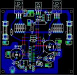
AM_Brownlow said:I recently built an 8 Channel Amp. Each module puts out about 65 Watts at 8 Ohms using a +/- 45 PS. The ops uses Lateral MOSFETS. These new chip amps are super quiet! High PSRR. Absolutely no HUM, HISS or motorboating. These are some great chips. There's not a whole lot of kits out there now, so I prototyped my own with some success I think.
I plan to use this multi amp to drive the LinkwitzLab Open Baffle Speakers which require all the same amp specifications.
Notice the attached file showing the bias pot. Only 30 ma of current through the MOSFETS with the heatsink/no fan.
Would like 100 ma.
It will work but you may need to play with the value of Rsb, 2.2k up to 20K or more and see what the differences are. You also need 0.1uF film caps at the supply pin of each FET. The gate resistor values may need adjustment to get them optimized. I would also add a resistor to the VBE multiplier from BiasP to the collector/Rb2 connection. This allows you to set a temperature independent bias voltage. Then you can adjust the values to get a correctly compensated bias voltage over termperature. 0.25ohm seems high for the source resistors, maybe 0.1ohm. If you want the output stage biased some where near 200mA then I'd suggest values of new resistor = 680 ohms, Rb2 = 750 ohms, and Rb1 = 205 ohms. This should get you a good starting point.
-SL
-SL
AndrewT said:Hi Pao,
to match Cin =10uF, Ci needs to be doubled. Use 470uF.
What does Rsb do?
The Vbe multiplier must be on the main heatsink, to temperature compensate the output FETs.
If you use +-50Vdc for the FETs, then +-55Vdc to +-58Vdc is adequate as a supply for the voltage amplifier. This could be regulated, but I have not seen any reports on the benefits of regulating the voltage amp and driver stages of this chip.
Hi
I am new to building amps so please excuse me for asking too many questions
According to specs LME49810 and MOSFETs pair ( SK1058/J162) can handle supply voltage safely up to +_100V and 200V respectively.
Having supply some ware +_50-60V are restricted due to power transformer availability or any particular reason?
Regards KC
Hi,kesee said:According to specs LME49810 and MOSFETs pair ( SK1058/J162) can handle supply voltage safely up to +_100V and 200V respectively.
the 1058 & 162 are 160Vds devices.
The absolute maximum supply rail voltage is +-80Vdc.
This may occur when the mains is at maximum tolerance and when the amp bias is turned down and/or one of the amps is disconnected (fused).
The maximum working voltage for the supply rails when mains is at nominal supply voltage and the bias is set correctly will be about +-73Vdc and that leaves some leaway for the exceptional conditions.
Fets generally require a driving voltage that is significantly above the source voltage. This results in less power from the amplifier when all stages are supplied from the same common rails.
This "lost" power can be released by running the voltage amp stage from higher supply rails as you suggested. The normal overhead adopted to get good power delivery is about 5V to 7V above the output supply rail voltage.
The 4702 can be run from this higher voltage supply but if you run it higher than necessary you gain nothing extra and the chip has to dissipate more heat. This may activate the protection circuits in the chip earlier than if running cold.
Hi Andrew,
So you are suggesting to have +_60V at the chip stage an to have +_50V at the MOSFET stage will give the best results?
Initially I am building a Sub woofer amp to drive my PC sound cards sub output. Now I am very much interested to build a complete true audio amp and listen to my LP collection
So you are suggesting to have +_60V at the chip stage an to have +_50V at the MOSFET stage will give the best results?
Initially I am building a Sub woofer amp to drive my PC sound cards sub output. Now I am very much interested to build a complete true audio amp and listen to my LP collection
Hi,
35Vac will give near 50Vdc.
Add on a 5Vac transformer and bridge rectify that 40Vac to give 58Vdc.
These would be near ideal for 100W into 8r0 or 200W into 4r0 if the PSU and amplifier are designed for this loading.
If you want to try regulating the chip supply then use a 9Vac transformer giving about 62Vdc. Regulate this down to 56Vdc.
These two schemes are best done with dual secondary transformers. Using a single rectifier on each winding allows all the PSU stages to remain separate and then connect the zero volt star together. This is the more flexible arrangement if you decide to regulate and also minimises power amp ripple in the HV low current supply.
AndrewT said:[
If you want to try regulating the chip supply then use a 9Vac transformer giving about 62Vdc. Regulate this down to 56Vdc.
These two schemes are best done with dual secondary transformers. Using a single rectifier on each winding allows all the PSU stages to remain separate and then connect the zero volt star together. [/B]
Hi Andrew,
Do you have any scamatic for the chip amp regulated PSU for +_ 55-60V
Regards KC
AndrewT said:There are dozens here
Hi Andrew,
Would like to share with us
it will be a great help to me
Regards
Thanks everybody, you have been very helpfull. I'll post again when I have some results to share. thanks again!
- Home
- Amplifiers
- Chip Amps
- LME49810 - a new cousin for LM4702