2 jumpers above one copper track.
Make it one jumper and two tracks.
Jumpers should be outside the component boundary.
U need to read about the value of the capacitor in other thread
Closer the capacitor to the outputs, the better it is.
The output FETs need to be fitted to a big heatsink. Think how u will fix it and correct as needed.
Gajanan Phadte
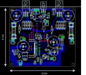
My version of the amp board
Hi folks!
Here is my first version of the amp board. It is assumed to be placed to the motherboard where is all the powering (high & opamp), signal connectors, power connector, output connector. And may be, mute and clip led connection.
In the front there is 4th order filters to be used for active filtering, if required.
Output Fets are open, fill free to chose proper ones. "big" el-caps are low esr-type.
There are still wrong cases in the feedback, input and output snubber. i am searching compos to update PWB.
Jpg's coming later for guys not owing free Eagle.
Thermal Management
I'm very impressed with the quality of work I see on this thread!
I couldn't help noticing that none of these designs have the LM49810 mounted on the same heatsink as the output transistors. Wouldn't it make sense to do so? That way the thermal protection and bias tracking features of the LM49810 can track the actual dissipation of the output devices.
My interest is in building a very compact and lightweight bass amplifier to play in jazz settings. 300watts into a heavy-duty 10" speaker in a 1 foot (or smaller...) cube is what I'm after. The chip amp will greatly simplify the power section thermal management in addition to providing very high fidelity.
Keep up the great work everyone!
Do NOT put the LME49810 on the same heat sink. Use a separate heat sink and keep it cool. Let the output stage heat up and down but try to keep the LME49810 pretty cool all the time. This will give best performance. The bias thermal compensation is done with transistors on the output stage heat sink. The LME49810 does not have any protection circuitry beyond some for itself. Check out the datasheet and you'll get more info there.
-SL
-SL
Re: Thermal Management
Here is something you need; a compact powerful module up to 1kW/4ohm and will play in jazz combo very well. 😉
Tedknowlegy said:I'm very impressed with the quality of work I see on this thread!
I couldn't help noticing that none of these designs have the LM49810 mounted on the same heatsink as the output transistors. Wouldn't it make sense to do so? That way the thermal protection and bias tracking features of the LM49810 can track the actual dissipation of the output devices.
My interest is in building a very compact and lightweight bass amplifier to play in jazz settings. 300watts into a heavy-duty 10" speaker in a 1 foot (or smaller...) cube is what I'm after. The chip amp will greatly simplify the power section thermal management in addition to providing very high fidelity.
Keep up the great work everyone!
Here is something you need; a compact powerful module up to 1kW/4ohm and will play in jazz combo very well. 😉
An externally hosted image should be here but it was not working when we last tested it.
An externally hosted image should be here but it was not working when we last tested it.
An externally hosted image should be here but it was not working when we last tested it.
Re: Thermal Management
No, the chip only needs to dissipate a few watts, so a small TO220 tag type heatsink is ample. A benefit of a separate heatsink is that the chip doesn't need to be electrically isolated with insulating washer, as it would need to be if mounted on the same heatsink as the power output devices.
The 150deg.C thermal protection is for the chip dice, not the external power output devices.
The bias tracking is external to the chip (Vbe multiplier transistor mounted on output devices and connected to BiasP and BiasM pins).
Tedknowlegy said:...I couldn't help noticing that none of these designs have the LM49810 mounted on the same heatsink as the output transistors. Wouldn't it make sense to do so? That way the thermal protection and bias tracking features of the LM49810 can track the actual dissipation of the output devices...
No, the chip only needs to dissipate a few watts, so a small TO220 tag type heatsink is ample. A benefit of a separate heatsink is that the chip doesn't need to be electrically isolated with insulating washer, as it would need to be if mounted on the same heatsink as the power output devices.
The 150deg.C thermal protection is for the chip dice, not the external power output devices.
The bias tracking is external to the chip (Vbe multiplier transistor mounted on output devices and connected to BiasP and BiasM pins).
Ed LaFontaine said:
Agreed.
Where?
Here:
"Tedknowlegy: My interest is in building a very compact and lightweight bass amplifier to play in jazz settings. 300watts into a heavy-duty 10" speaker in a 1 foot (or smaller...) cube is what I'm after."
😀
Ed LaFontaine said:
You're bloody right 😀
hey Lazy Cat what discrete modules did you use for each amp? and how did u get such a huge power? 1kw oh my god.......
did u parallel the output devices?
please tell me dude I need to build a very high quality amp for a scanspeak revelator woofer... 26w....
thanks,
Ken
did u parallel the output devices?
please tell me dude I need to build a very high quality amp for a scanspeak revelator woofer... 26w....
thanks,
Ken
rhythmdiy said:hey Lazy Cat what discrete modules did you use for each amp? and how did u get such a huge power? 1kw oh my god.......
did u parallel the output devices?
please tell me dude I need to build a very high quality amp for a scanspeak revelator woofer... 26w....
thanks,
Ken
Some real measured and tested data: power up to 1kW/4ohm at +100V/-100V, output impedance 4mohm/1kHz, so the dumping factor is 2000 at 8 ohms, 8 output transistors Toshiba 2SA1987/2SC5359 per module. Sounds great.
First implementation Oct 2007 in Technics SA-E3 power amp: +85V/-85V, 380Wrms/8ohm, sounds great too. 🙂
An externally hosted image should be here but it was not working when we last tested it.
An externally hosted image should be here but it was not working when we last tested it.
An externally hosted image should be here but it was not working when we last tested it.
That looks really nice 😀 Big analog meters are cool!
Do you have speaker protection? If you do, how did you do it at that voltage? (Relays won't be able to break that if they aren't huge)
Do you have speaker protection? If you do, how did you do it at that voltage? (Relays won't be able to break that if they aren't huge)
short circuit protection with lme49810
a few questions on this subject:
Let suppose we design an output stage with BJT's in the T topology ( Leach amp). SOA protection circuit will require to short circuit base of the driver in case of short circuit. This will short circuit the source and sink output of the LME 49810.
Can we short circuit the mute input instead and will this be fast enough in protecting the output devices?
Will short circuiting the source and sink pins to ground blow the chip our activate the thermal protection? If the later is the case, then can it be combined with the mute control for faster but still safe protection?
Jean-Pierre
Re: short circuit protection with lme49810
It bears more investigation.
I've looked at this with the LM4702 and the LM3886 and LM4780 (but not the critter in question, but I am sure it is a reasonably close analog). The mute removes the drive almost instantaneously, you might want to charge the pin with an electrolytic so that you get a couple of time constants before the device goes back on.JPV said:a few questions on this subject:
Let suppose we design an output stage with BJT's in the T topology ( Leach amp). SOA protection circuit will require to short circuit base of the driver in case of short circuit. This will short circuit the source and sink output of the LME 49810.
Can we short circuit the mute input instead and will this be fast enough in protecting the output devices?
Will short circuiting the source and sink pins to ground blow the chip our activate the thermal protection? If the later is the case, then can it be combined with the mute control for faster but still safe protection?
Jean-Pierre
It bears more investigation.
Re: short circuit protection with lme49810
There were some distortion plots posted earlier in this thread I think. They were taken with different resistors on the output of the driver chip and suggest that its outputs are at least current limited at the speced 50mA. 🙂
JPV said:a few questions on this subject:
Let suppose we design an output stage with BJT's in the T topology ( Leach amp). SOA protection circuit will require to short circuit base of the driver in case of short circuit. This will short circuit the source and sink output of the LME 49810.
Can we short circuit the mute input instead and will this be fast enough in protecting the output devices?
Will short circuiting the source and sink pins to ground blow the chip our activate the thermal protection? If the later is the case, then can it be combined with the mute control for faster but still safe protection?
Jean-Pierre
There were some distortion plots posted earlier in this thread I think. They were taken with different resistors on the output of the driver chip and suggest that its outputs are at least current limited at the speced 50mA. 🙂
there has been a few references to schematic in this thread that uses the mute input to shutdown the drive.
the disadvantage is that as it works very fast it will go on and off, in case of over-current/short circuit with the speed of the circuit response so without capacity on the mute pin it will be very fast indeed.
High current oscillation in the output stage might not be so funny... some hysteresis, and time delay could be good.
Or make it a manual-reset-before-restart again, just like an automatic fuse.
rikkitikkitavi said:there has been a few references to schematic in this thread that uses the mute input to shutdown the drive.
the disadvantage is that as it works very fast it will go on and off, in case of over-current/short circuit with the speed of the circuit response so without capacity on the mute pin it will be very fast indeed.
High current oscillation in the output stage might not be so funny... some hysteresis, and time delay could be good.
Or make it a manual-reset-before-restart again, just like an automatic fuse.
But then again, it would be trivial to make it fast shut-down, delayed reset. That would be a nice option.
Jan Didden
- Home
- Amplifiers
- Chip Amps
- LME49810 - a new cousin for LM4702