AndrewT said:Hi KC,
7k input impedance is rather low.
Your source must be Rs<<700r and capable of driving 7k to +10db above full input voltage, i.e. >=6Vpk. 10Vpk would be even better for headroom.
Andrew, let me understand correctly - 10Vpk is the amplitude value or full range - from -5V to +5V (dowble amplitude)?
His output stage has the gain about 29, if 10Vpk is an amplitude, it will be 290V amplitude at the output, that impossible.
If 10Vpk is a double amplitude, it will be 145V amplitude at the output, that is also impossible.
Max VCC of the 49810 is 100V, with mosfets at the output, you can obtain maximim (VCC-8) amplitute, so 92V, (that with 8 Ohn load will be 530W).
92V/29= 3.2V max amplitude at the input.
Where I'm wrong ?
BTW, 7k input is not so low, any good OP is able to work with 3V amplitute on the 7k load.
Another question - is the cap C1 100nF (between "source" and "sink") necessarry ?
Hi,
the power amp could have an output voltage of 40Vpk (=80Vpp). Note my use of Vac, Vpk, Vpp avoids all confusion.
The power amp has a gain of 25times (if I have read 24k & 1k0 correctly).
It needs 1.6Vpk at the input (I allowed 2Vpk in my previous post) to produce maximum power of 100W into 8ohms.
This is the drive requirement from the source. 5Vpk to 6Vpk into 7k. Yes, you are right, a properly designed preamp capable of driving low Zin, this is not a problem, for a cheapskate system it becomes a problem.
I further suggested that ability to go to 10Vpk from the source would be even better. This would give about 14db of headroom for any transient signal or transient interference spike that passes through the pre-amp without clipping.
This headroom is not there to drive the power amp into clipping and/or overload. It is there to give the best chance to send a clean signal to the power amp and then let the passive input filtering in the power amp reduce the level of the transient that the following amp is incapable of reproducing.
A decent opamp (not rail to rail which has necessarily compromised performance) operating on +-10Vdc can usually go to 6Vpk and +-15Vdc allows near 10Vpk output. If the current ability of the opamp allows, then those maxima would suit the headroom quoted earlier.
the power amp could have an output voltage of 40Vpk (=80Vpp). Note my use of Vac, Vpk, Vpp avoids all confusion.
The power amp has a gain of 25times (if I have read 24k & 1k0 correctly).
It needs 1.6Vpk at the input (I allowed 2Vpk in my previous post) to produce maximum power of 100W into 8ohms.
I said allow a pre-amp headroom of +10db (=3.1times) on that maximum input signal and the pre-amp should be able to drive Zin to at least 3.1*1.6Vpk=5.1Vpk (or using 2Vpk*3=6Vk).to +10db above full input voltage,
This is the drive requirement from the source. 5Vpk to 6Vpk into 7k. Yes, you are right, a properly designed preamp capable of driving low Zin, this is not a problem, for a cheapskate system it becomes a problem.
I further suggested that ability to go to 10Vpk from the source would be even better. This would give about 14db of headroom for any transient signal or transient interference spike that passes through the pre-amp without clipping.
This headroom is not there to drive the power amp into clipping and/or overload. It is there to give the best chance to send a clean signal to the power amp and then let the passive input filtering in the power amp reduce the level of the transient that the following amp is incapable of reproducing.
A decent opamp (not rail to rail which has necessarily compromised performance) operating on +-10Vdc can usually go to 6Vpk and +-15Vdc allows near 10Vpk output. If the current ability of the opamp allows, then those maxima would suit the headroom quoted earlier.
The seminars will be pretty short but some good info. Check out the National booth at AES as they will have a demo mono block amp using the LME49810 and a room for listening test of the mono blocks. I believe these will soon be released as reference designs with all supporting documentation. Some of the guys in the booth will be very knowledgeable as they are engineers and not marketing guys. If you want to talk to the guys that built the amp then this is the place.
-SL
-SL
jackinnj said:An externally hosted image should be here but it was not working when we last tested it.
Note that this is the LM4702B, which appears to have significantly lower distortion than the C.
panson_hk said:This is the schematic of my design under development. The output BJT is OnSemi ThermalTrak, NJL3281D and NJL1302D. The feedback network and protection circuit is a copy of that of the Leach Amp.
I will use prototyping board to try the design before going to fab the PCB.
Hi Panson,
I found your report titled"Using LME49810 to Build a High-Performance". I was wondering do you have a BoM for the circuit.
Cheers
Paul
LME49810
I recently built an 8 Channel Amp. Each module puts out about 65 Watts at 8 Ohms using a +/- 45 PS. The ops uses Lateral MOSFETS. These new chip amps are super quiet! High PSRR. Absolutely no HUM, HISS or motorboating. These are some great chips. There's not a whole lot of kits out there now, so I prototyped my own with some success I think.
I plan to use this multi amp to drive the LinkwitzLab Open Baffle Speakers which require all the same amp specifications.
Notice the attached file showing the bias pot. Only 30 ma of current through the MOSFETS with the heatsink/no fan.
Would like 100 ma.
Attachments

Hi Andrew,Altor
Thanks for giving me very important advice and I am very much appreciated.
I am not a electronic Engineer but keen hobbyist with a background of IT specialist (AACS) and Mechanical Engineering
I think due to expanding of the broadband connectivity and the development in the web TV broadcasting, quality sound system for the PC is a necessity in the future.
Intention was to extend my PC sound card’s capability to have 5.1 high quality medium power home theater sound system using 5 channels (front, rear, center) of LM1875 and LME49810 + 1530/201 FET driven Sub woofer amp
So that was the reason to have the 29db gain as out put of the sound card is around 2-3Vpk and also to have 1 to 3 pairs of FETs (100 -150W out put) depending on the requirement to drive the out put with +_60V supply to drive 8 ohm load
the bias FET is on the heatsink.
Further advice is welcome and very much appreciated.
Regards KC
AM_Brownlow, I like those little modules. They look so simple. What FETs are you using? They look like they could be Renesas which might mean the 1058/162 pair. What did you think of the sound quality of the completed amp? Any measurements?
-SL
-SL
SL
You are correct on the Renasis FETS. No formal testing on the completed system yet. My inventory of test equipment is an O-scope and an HP Signal Gen. I cannot see any so called crossover distortion on the scope-but really need a distortion analyzer.
Sounds great and very pleased. I'm using back-to-back 22uF tantium caps as input filtering, which provides a very low end Responce. I had to adjust my DC protection sensitivity a little. Each module uses three RF Mica caps in the circuit topolgy. I basically followed National's design guide with a little change in gain.
Good repor with "ExpressPCB" who developed the Boards for me. I have pictures of the insides of the chassis if you are interested. Eight modules required a huge Power supply an interesting resistor bias and fuse arangement. I also built the AmpsLab LM60 before I built these. I think my modules sound better because of the higher slew rate and no background noise.
Thanks for the feedback
Mark
Hi everyone.
Can anyone tell me the best MOSFET pair ( in cascade )to be used LME49810 to achieve 100 – 150W at +_60V to 8 ohm load
Regards, KC
Can anyone tell me the best MOSFET pair ( in cascade )to be used LME49810 to achieve 100 – 150W at +_60V to 8 ohm load
Regards, KC
Hi,kesee said:Hi everyone.
Can anyone tell me the best MOSFET pair ( in cascade )to be used LME49810 to achieve 100 – 150W at +_60V to 8 ohm load
Regards, KC
150W into 8r0 needs 49Vpk from the output.
I don't think you can quite get that with FETs for the output devices with the chip running on +-60Vdc common supply rails.
The losses through the various stages stack up too high.
40Vpk is easily achievable giving 100W into 8r0.
With care in the selection of components 45Vpk should be achievable giving 126W into 8r0. This would probably require two pair of lateral FETs for reliable current output to the load.
If you run the outputs from +-60Vdc and the chip from +-65Vdc you should easily get to 150W into 8r0 and maybe more. I would suggest 3pair of 2sj162/k1058 for this duty. Run the output bias at 400mA and use a big sink to keep the temperature down.
AndrewT said:Hi,
150W into 8r0 needs 49Vpk from the output.
I don't think you can quite get that with FETs for the output devices with the chip running on +-60Vdc common supply rails.
The losses through the various stages stack up too high.
40Vpk is easily achievable giving 100W into 8r0.
With care in the selection of components 45Vpk should be achievable giving 126W into 8r0. This would probably require two pair of lateral FETs for reliable current output to the load.
If you run the outputs from +-60Vdc and the chip from +-65Vdc you should easily get to 150W into 8r0 and maybe more. I would suggest 3pair of 2sj162/k1058 for this duty. Run the output bias at 400mA and use a big sink to keep the temperature down.
I can confirm that the THD% doesn't get much better when you run the bias hotter...but you will keep the room warm through those long Scottish winters by running the bias at 400mA.
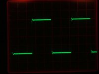
Thought I'd show you guys a picture of a sqaure wave at 20 KHz 20 Volts Peak to Peak of one of the amp modules. (LME 49810 directly driving a pair of 1058/162. (My old Tektronix taken with a Fuji FinePIX ... not the best).
Guess I'm a little exicted about the results. 😀
Mark
Guess I'm a little exicted about the results. 😀
Mark
Attachments
paokakis said:Hello I am new to amplifier designs and I want to know if this schematic is ok? Can anyone tell?
Hi paokakis,
have you complete your amp and how does it sound?
AndrewT said:Hi,
40Vpk is easily achievable giving 100W into 8r0.
With care in the selection of components 45Vpk should be achievable giving 126W into 8r0. This would probably require two pair of lateral FETs for reliable current output to the load.
If you run the outputs from +-60Vdc and the chip from +-65Vdc you should easily get to 150W into 8r0 and maybe more. I would suggest 3pair of 2sj162/k1058 for this duty. Run the output bias at 400mA and use a big sink to keep the temperature down.
Hi Andrew,
I have adjusted the sch. as you suggested. with 1 -2V input is it possible to get around 100 to 125W with +_60V into 8r0 load?
I have attached Eagle light schamatic
Regards KC
Attachments
Hi everyone,
Has anybody tried building pcb s for our amps?
I just found this on the web.
very interesting DIY way of making your own pcb
pdf file is too big so I am attaching the word file
I can send the complete pdf if anyone needs by e mail
Regards KC
Has anybody tried building pcb s for our amps?
I just found this on the web.
very interesting DIY way of making your own pcb
pdf file is too big so I am attaching the word file
I can send the complete pdf if anyone needs by e mail
Regards KC
Attachments
Hi,kesee said:Hi everyone,
Has anybody tried building pcb s for our amps?
I just found this on the web.
very interesting DIY way of making your own pcb
pdf file is too big so I am attaching the word file
I can send the complete pdf if anyone needs by e mail
Regards KC
how close is this PCB printing method to Tom Gootee's?
What transformer is giving +-60Vdc?kesee said:100 to 125W with +_60V into 8r0 load?
AndrewT said:What transformer is giving +-60Vdc?
Hi Andrew,
I think it is from Gootee.
I downloaded it from this web add http://www.fullnet.com/u/tomg/gooteepc.htm
I have not tried it as yet. did you?
As for the transformer 90V ac sec with center tap or 2x 45 V
Regards KC
- Home
- Amplifiers
- Chip Amps
- LME49810 - a new cousin for LM4702