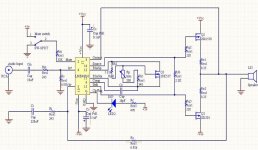
CJ900RR said:Well its shure looks like the LME49810... he uses 10 output transistors and claims 1000W into 4 ohm. To bad its on russian. Cant understand it 🙂
Is the numbers of outputs-transistors that gives you more power?
Good suggestion I also think it's LME49810 driver, what amazes me is such small volume/amount of material for such power level. As A-B class amp it has probably some 40-50W idle dissipation and for full power level of 1000W/4ohms it would need a big heatsink or maybe vented heatsink tunnel. Certainly should be taken a great care to design the cooling system for purpose one would use this amp.

The language of the advertisement is Slovenian, not really well known in global scale.

CJ900RR I'm sorry to overlook your question about the amount of output transistors vs. power level. As I knew from the high school, power dissipation on the speaker depends of the voltage level and current supply capability at amp output connection.
First and most important is that you have power supply unit with proper voltage/current level to enable desired Watt's and than the number of carrefully selected output transistors to handle current level and power dissipation which should never overcross SOA (Safety Operating Area) of paralleled output devices. It's also very important that you have quality voltage gain stage to ensures stability and low output impedance (dumping) of the amp. All together forms a synergy to give you desired power level of the amp. 😉
First and most important is that you have power supply unit with proper voltage/current level to enable desired Watt's and than the number of carrefully selected output transistors to handle current level and power dissipation which should never overcross SOA (Safety Operating Area) of paralleled output devices. It's also very important that you have quality voltage gain stage to ensures stability and low output impedance (dumping) of the amp. All together forms a synergy to give you desired power level of the amp. 😉
An externally hosted image should be here but it was not working when we last tested it.
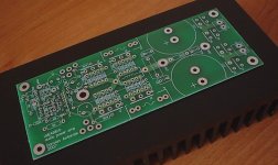
Today I bought two ProJet Power Modules to verify specifications from this advertisment and make stereo power amp later. I hope they'll sound as good as they look. I intend to put them in metal case of the old Technics power amplifier with big VU meters. But first I'll perform measurements with some spare power supply on big heatsink 😀
Hi,
That PCB looks really neat. First time I've seen white.
I also like the clamping bar holding the ten output devices.
But how do you remove them from the heatsinking block?
That PCB looks really neat. First time I've seen white.
I also like the clamping bar holding the ten output devices.
But how do you remove them from the heatsinking block?
veteran said:My boards for this amplifier are finally ready 😉
Hi Veteran
Do you have plans for offering these boards?
(The ones I bought from you were great!)
Please let us know of your test results.
Cheers!
AndrewT said:Hi,
That PCB looks really neat. First time I've seen white.
I also like the clamping bar holding the ten output devices.
But how do you remove them from the heatsinking block?
 Vice versa than it was produced. I think they had in mind to be difficult or even immpossible to do it and not damage PCB. How would you remove output transistors from LM3886? It looks it meant to be sealed module.
An externally hosted image should be here but it was not working when we last tested it.
An externally hosted image should be here but it was not working when we last tested it.
An externally hosted image should be here but it was not working when we last tested it.
Some images from the testing session of two ProJet Power Modules I own. The sound is very promising at powering on and well controlled and bright when IC gets to 55°C. Quiescent current is app. 100mA through each output transistor. I started at 140V from rail to rail and clipping was just 3V under rail voltage.
You can also see old Technics power amp case in where two modules will be installed soon.

Report follows ASAP.

Lazy Cat said:CJ900RR I'm sorry to overlook your question about the amount of output transistors vs. power level. As I knew from the high school, power dissipation on the speaker depends of the voltage level and current supply capability at amp output connection.
First and most important is that you have power supply unit with proper voltage/current level to enable desired Watt's and than the number of carrefully selected output transistors to handle current level and power dissipation which should never overcross SOA (Safety Operating Area) of paralleled output devices. It's also very important that you have quality voltage gain stage to ensures stability and low output impedance (dumping) of the amp. All together forms a synergy to give you desired power level of the amp. 😉
Thank you for that claryfication Lazy Cat. It's allways appreciated to learn from more experienced people like you, Andrew T and many more 🙂
Nice to see your amp being build. Please let us hear what you think about the sound and other stuff.
I have to say that LM4702 from now is dead for me - LME49810 is amazing chip!
No oscillations and noises on my PCB even without additional capacitors on input and feedback. Clear sound. Hi output power and available bias voltage.
I'm driving standard MOSFET pair now but with 2SK1530/2SJ200 should be even better 😀
No oscillations and noises on my PCB even without additional capacitors on input and feedback. Clear sound. Hi output power and available bias voltage.
I'm driving standard MOSFET pair now but with 2SK1530/2SJ200 should be even better 😀
An externally hosted image should be here but it was not working when we last tested it.
veteran said:I have to say that LM4702 from now is dead for me - LME49810 is amazing chip!
No oscillations and noises on my PCB even without additional capacitors on input and feedback. Clear sound. Hi output power and available bias voltage.
I'm driving standard MOSFET pair now but with 2SK1530/2SJ200 should be even better 😀
An externally hosted image should be here but it was not working when we last tested it.
 I can not more agree with you. Go on Veteren !
Dear Veteran, T1 should be instaled on the big heatsink where power transistors are placed. You know T1 intention? I'm sure yes. 
I just stumbled on this thread. I've a question that I couldn't find an answer to in the datasheet or by scanning the thread. (I may have just missed it.) What is the function of the Osense pin? From the first data sheet diagram it looks like if connected to the speaker output it will mute the chip in the event that the output is shorted. Is that correct?
sam9 said:I just stumbled on this thread. I've a question that I couldn't find an answer to in the datasheet or by scanning the thread. (I may have just missed it.) What is the function of the Osense pin? From the first data sheet diagram it looks like if connected to the speaker output it will mute the chip in the event that the output is shorted. Is that correct?
No it's not correct. You should look to FIGURE 2. - Inside chip block schematics in LME datasheet and you'll understand the Osense pin function: when mute is on (if there is no current to mute pin) than input OP amp is disabled and Osense OP amp is enabled to drive output to zero signal instantainously. That means when you go to mute state, the audio signal is immediately muted without any clicks or pop-up noises at output.
Mute function does not influence the bias in any prospective. Bias current is independent and stays the same in mute state. This is somehow weird and certainly demands synchronisation between power up/down situation with mute state function.
 This would also be interested to many readers: There is no need to zero bias current at mute state.
Why? Osense pin senses the output in all time and together with mute function acts in a way that there are no pop-up noises at power up/down.
How it acts in reality? When I power up the ProJet Power Module music starts immediately without unwanted noises and when the power goes off, the music stops in a blink of an eye. Also without unwanted noises, simply goes to silence.
Satisfied? Completely!

Clamp and thermal shutdown functions work fine in this chip.
Lazy Cat, MOSFET transistors if you ensure them wright conditions (bias voltage and some big heatsink) don't need the bias transistor on the same heatsink - for example Mr. Pass amplifier 😉
If somebody is interested I have about 20 boards for this project - I always have to order more to keep the price on reasonable level.
I can also order some heat sinks for this design - they fit perfectly on LME49810.
Lazy Cat, MOSFET transistors if you ensure them wright conditions (bias voltage and some big heatsink) don't need the bias transistor on the same heatsink - for example Mr. Pass amplifier 😉
If somebody is interested I have about 20 boards for this project - I always have to order more to keep the price on reasonable level.
An externally hosted image should be here but it was not working when we last tested it.
I can also order some heat sinks for this design - they fit perfectly on LME49810.
An externally hosted image should be here but it was not working when we last tested it.
Hi,veteran said:.......MOSFET transistors if you ensure them wright conditions (bias voltage and some big heatsink) don't need the bias transistor on the same heatsink - for example Mr. Pass amplifier 😉
......
Lateral FETs can be used without temperature compensation on the gate bias voltage. Vertical FETs should always use temperature compensation. k1530/j200 are a version of a vertical FET and should have Tcomp.
Veteran, what kind of heat sinks are those you found for that chip? They are very interesting. Where do you get them?
Very nice work on your layout. I bet it sounds great.
Cheers!
Russ
Very nice work on your layout. I bet it sounds great.
Cheers!
Russ
- Home
- Amplifiers
- Chip Amps
- LME49810 - a new cousin for LM4702