Russ White said:Veteran, what kind of heat sinks are those you found for that chip? They are very interesting. Where do you get them?
Very nice work on your layout. I bet it sounds great.
Cheers!
Russ
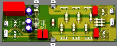
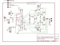
I optimized this PCB to get similar track length for both rails and ground.
Heat sink: STONECOLD, HS-012 (cost about 1$ here).
Attachments

IVANAUDIO said:
Nice schematic but to complicated regarding thermal compensation. Instead so many diodes you can use only one transistor for thermal bias compensation, or maybe power transistors are not on the same heatsink?
Also C1, L1, C3, L2 are very exotic on this location. Can be done more accurate differently. 😀
CJ900RR said:I have been working on my own layout for a while. Any suggestions?
Maybe you should avoid all caps in signal/feedback path and implement DC servo on the PCB.
Regarding PCB: maybe you should exactly follow schematic's point to point or star like connections and therefore avoid possible interference currents. If you look to Veteran's PCB you'll know what I mean. On ProJet Power Module PCB there are very exact point to point and extremely short lenghts of all connections.

Lazy Cat said:
Maybe you should avoid all caps in signal/feedback path and implement DC servo on the PCB.
Regarding PCB: maybe you should exactly follow schematic's point to point or star like connections and therefore avoid possible interference currents. If you look to Veteran's PCB you'll know what I mean. On ProJet Power Module PCB there are very exact point to point and extremely short lenghts of all connections.
I can agree with you about removing caps and use dc-servo instead, and using star-ground. But I must question your opinion about point to point connections. Do you really think that 1cm connection distance will make a big difference from 2-3 mm distance? I mean, so mutch difference that you can hear it? If you think about it, you still have a huge difference in length if the resistors grid is 10, than if it's 7. That's a difference of 6 mm even if your using point to point like connections.
Im dont want to offend you or anything. Im only wondering 🙂
Lazy Cat said:
Nice schematic but to complicated regarding thermal compensation. Instead so many diodes you can use only one transistor for thermal bias compensation, or maybe power transistors are not on the same heatsink?
Also C1, L1, C3, L2 are very exotic on this location. Can be done more accurate differently. 😀
He does not use any diodes! There are ThermalTrak ttransistors fron the OnSemi (Motorola) with built-in diodes.
These transistors were especially invented to audio amplifiers with thermal compensation.
C1L1C3L2 Yury used for better frequensy responce.
(to my mind, it is good without).
What I think need to be added to all schematics - short circuit protection. I've lost 4 chips during my experiments. The best result you can see at the schematic - with short and DC protection, with DC-Servo and electronic volume control.
Attachments
Thermal-Trak transistors or separate diodes, what's the difference? The lenght of all "diode" connection and possible addition of interferences to basic audio signal is unacceptable. This is not an audio solution whatsoever, maybe for some PA or industrial solutions. 
C1L1C3L2 - better frequency response with passive filter in this location? I don't think so. I suppose their intention is frequency compensation to avoid oscilations of a current stage. But as I said, there are better solutions for this problem.
C1L1C3L2 - better frequency response with passive filter in this location? I don't think so. I suppose their intention is frequency compensation to avoid oscilations of a current stage. But as I said, there are better solutions for this problem.
Dear CJ900RR, there are scientific rules or recommendations how to connect wires or PCB connections to avoid interference currents and not only in audio industry. All current connections should follow these rules not only ground or supply lines.
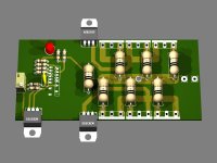
One example from your PCB: driver to three bases connection can be done more optimized; driver line should be connected in the middle of three bases, maybe from bottom layer. 😉
One example from your PCB: driver to three bases connection can be done more optimized; driver line should be connected in the middle of three bases, maybe from bottom layer. 😉
Lazy Cat said:Thermal-Trak transistors or separate diodes, what's the difference?
The distance (thermal impedance) between the transistor and the thermal sensor.
This is not an audio solution whatsoever
I know, that WE300B or PassLab's Zen - are the better solutions 🙂
Lazy Cat said:Dear CJ900RR, there are scientific rules or recommendations how to connect wires or PCB connections to avoid interference currents and not only in audio industry. All current connections should follow these rules not only ground or supply lines.
One example from your PCB: driver to three bases connection can be done more optimized; driver line should be connected in the middle of three bases, maybe from bottom layer. 😉
Ok veteran. Thank you. Is this better? Or have I missunderstod you? The via goes to one of the pad's to the right. Speaker out. The board is not finished yet so everything isnt there yet.
Attachments
Hi,
is this a double sided PCB?
If so, then the To220 and To247 devices can be inserted from the other side and soldered on the component side.
Makes for much easier attachment to the heatsink.
is this a double sided PCB?
If so, then the To220 and To247 devices can be inserted from the other side and soldered on the component side.
Makes for much easier attachment to the heatsink.
AndrewT said:Hi,
is this a double sided PCB?
If so, then the To220 and To247 devices can be inserted from the other side and soldered on the component side.
Makes for much easier attachment to the heatsink.
Hi Andrew. Yes it's duoble-sided and they are meant to be mounted from the other side. I did not find the corresponding package for that in Eagle3D, so that's why it's mounted at the top side in the picture.
Great photos on this thread!
Awesome pictures, that's a nice looking design. I have a few samples at home of the LME49810 and want to start tinkering. Cool!
I just got this email link forwarded from a friend - seems National Semiconductor is doing Audio Design Seminars at AES this year.
I wonder how good these will be, I figure anything free is not a bad deal. I don't know how the heck I'll be able to pay for parking around that location. But maybe they'll have some good freebies there too.
http://www.national.com/rsvp/audioseminar
Hi everybody,
I've read some of the your dialogues and seen some great pictures on this forum.
This is great and I am glad that I found this.
I want to build a power amp using this driver but I didn't see much design info or app. notes on the National website.

Does anyone have a trusting schematic for a high power application of the LME49810?
 ...or maybe some links where I can find some information for a good choice of transistors and their configuration?
Thanks.
What is Monkey's web address?
I've read some of the your dialogues and seen some great pictures on this forum.
This is great and I am glad that I found this.
I want to build a power amp using this driver but I didn't see much design info or app. notes on the National website.
Does anyone have a trusting schematic for a high power application of the LME49810?
...or maybe some links where I can find some information for a good choice of transistors and their configuration?Thanks.
What is Monkey's web address?
Re: Great photos on this thread!
Thanks for the link. The Boston location is in my home town.
just got this email link forwarded from a friend - seems National Semiconductor is doing Audio Design Seminars at AES this year.
I wonder how good these will be, I figure anything free is not a bad deal. I don't know how the heck I'll be able to pay for parking around that location. But maybe they'll have some good freebies there too.
http://www.national.com/rsvp/audioseminar [/B]
Thanks for the link. The Boston location is in my home town.
LME49810 driven MOSFET amp
I am a newbie to DIT Audio forum.
I have gathered info from the forum and designed a Amp.
I would be much appreciated if anyone have a look at it and give me comment on the attached schematic.
Thanks
Kesara de Costa
Sri Lanka
I am a newbie to DIT Audio forum.
I have gathered info from the forum and designed a Amp.
I would be much appreciated if anyone have a look at it and give me comment on the attached schematic.
Thanks
Kesara de Costa
Sri Lanka
Attachments
Hi KC,
7k input impedance is rather low.
Your source must be Rs<<700r and capable of driving 7k to +10db above full input voltage, i.e. >=6Vpk. 10Vpk would be even better for headroom.
The NFB roll-off time constant is shorter than the high pass filter on the input. If you keep the input @ 70mS then change the NFB to >=100mS i.e. use 470uF.
Have you considered running the chip voltage amp from a higher rail voltage for driving the 201/1530 FETs?
3pair output stage, what supply voltage and what speaker impedance? Match the FETs into upper group and lower group of Vds at your planned bias current. Might be better to order 10 of each to allow closer matching and discard the rogues. Or use them singly on some other projects.
Is the bias FET on the heatsink?
Some are using a cap on the mute to give a slow unmute at switch on.
Please do fit an RF low pass filter to the input. I usually recommend between 0.5uS and 1.5uS.
- Home
- Amplifiers
- Chip Amps
- LME49810 - a new cousin for LM4702