Re. VLSI
Thank you for your support !
The existence of the capacitance, high-frequency distortion rate will be improved. Value increases, the transistor base-base of the lower impedance.
NS will be published LME49830, High Fidelity Driver
for MOSFETS
VLSI said:Hi monkey29
Great to see you are developing a PCB for the LME49810 chip so soon.
Tony and I are very impressed with your work with the LM4702 and are very excited to try your LME49810
Board as soon as it is available.
I have built two LM4702 amps with my own design boards and Tony and I have built one each with yours.
Although they basically all sound the same, There are slight differences in the way they sound and it is hard to say exactly why.
I prefer not to say which ones sound the best until I have determined why.
I have a question! In the NS applications note AN-1490 for the LM4702 NS have specified a 15nf/1250v polypropylene capacitor across source and sink. I note you have used 100nf/100v “orange drop?polyester in your design and it is across the trimmer! I have moved the capacitor to the original NS position and replaced it with 15nf/300v mica (this is a big cap for a mica but I just happened to have some) and I am sure this improves the sound.
Why have NS specified such a high quality capacitor for this application?
Also would you consider developing a compact LME49810 board for just one pair of Darlington or MOSFET transistors without drivers and DC coupled throughout.
I know I should try and develop it myself but your boards, as so neat it’s hard to compete.
Keep up the good work.
Greg
Thank you for your support !
The existence of the capacitance, high-frequency distortion rate will be improved. Value increases, the transistor base-base of the lower impedance.
NS will be published LME49830, High Fidelity Driver
for MOSFETS
Attachments


Will there be a version with 10 (2 x 5) output transistor ? Would be really nice for heavy PA use.
Yay, NS finally did a news release for the LME49810 on 23 July 2007, see http://www.national.com/news/item/0,1735,1269,00.html
The news release for the new LME49860 dual +/-22V opamp is linked from that page. Its an uprated LME49720 (aka LM4562).
Its spreading like wild-fire around the electronics news web sites.
The news release for the new LME49860 dual +/-22V opamp is linked from that page. Its an uprated LME49720 (aka LM4562).
Its spreading like wild-fire around the electronics news web sites.
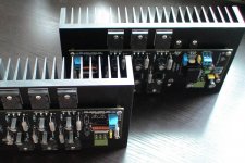
This is the schematic of my design under development. The output BJT is OnSemi ThermalTrak, NJL3281D and NJL1302D. The feedback network and protection circuit is a copy of that of the Leach Amp.
I will use prototyping board to try the design before going to fab the PCB.
I will use prototyping board to try the design before going to fab the PCB.
Attachments
Will the protection work? The datasheet doesn't say the LME49810 is current limited. Do you know if it is?
Hi monkey29,
what a chance. I wrote you today an email to your office, in the hope that they will understand english because the homepage i found was all in chinese ... and now i find you here ... Please contact. I am interested in a pair of LME49810 Amps. Are they finshed allready with heatsink or do i need to solder ?
Wich Power Supply does this set need ?
Thanks in advance for your efforts
Michael
megajocke said:Will the protection work? The datasheet doesn't say the LME49810 is current limited. Do you know if it is?
The protection is for the output stage.
Hi,panson_hk said:.........The feedback network and protection circuit is a copy of that of the Leach Amp........
the Leach protection has omitted a resistor to rail.
The Leach protection locus has a constant current characteristic when Vce>~Vrail, i.e.single slope. This allows overload of the output transistors into reactive loads.
Go look at the Leach clone thread for the location of the extra resistor for true two slope protection.
Better still ask Mikeks for a copy of his paper on protection schemes and how to calculate the component values. He also shows a better method of allowing transient signals through without triggering the protection.
Hi Dear Monkey29 & Panson_HK:
I am editor for a HiFi & DIY Magazine in Beijing, I wish you can write a artical about your LME49810 jobs for my magazine. could you please send a email to me?
my email is: radio@radio.com.cn
Thank you all!
I am editor for a HiFi & DIY Magazine in Beijing, I wish you can write a artical about your LME49810 jobs for my magazine. could you please send a email to me?
my email is: radio@radio.com.cn
Thank you all!
panson_hk said:
The protection is for the output stage.
You are missing the point. If the output stage protection activates it works by shunting away drive current from the VAS in the case of the Leach or the chip in this amplifier. The VAS in the Leach is current limited so it won't blow up when the output stage protection activates and shorts its output to ground. So I ask again, is the chip current limited?
megajocke said:You are missing the point. If the output stage protection activates it works by shunting away drive current from the VAS in the case of the Leach or the chip in this amplifier. The VAS in the Leach is current limited so it won't blow up when the output stage protection activates and shorts its output to ground.
So I ask again, is the chip current limited?
Yes, LME49810 spec is 50mA output current capability, which is much more than typical VAS's.
megajocke said:
You are missing the point. If the output stage protection activates it works by shunting away drive current from the VAS in the case of the Leach or the chip in this amplifier. The VAS in the Leach is current limited so it won't blow up when the output stage protection activates and shorts its output to ground. So I ask again, is the chip current limited?
Thanks for pointing this potential problem. My current idea is put the chip in mute mode and move D4/D3 after R6/R7 (base of Q1/Q2).
Does anyone know if it is current limited or not? It kind of sucks if it isn't, really. If it is current limited at 50mA, it wouldn't matter much that this current is higher than what a typical VAS can source/sink. The internal diagram does not show any current limiting, but it is a simplified diagram and these often omit stuff like current limiting. So it might still have it.
megajocke said:Does anyone know if it is current limited or not? It kind of sucks if it isn't, really. If it is current limited at 50mA, it wouldn't matter much that this current is higher than what a typical VAS can source/sink. The internal diagram does not show any current limiting, but it is a simplified diagram and these often omit stuff like current limiting. So it might still have it.
No it is not current limited. At least according to the design engineer I called to ask.
- Home
- Amplifiers
- Chip Amps
- LME49810 - a new cousin for LM4702