Lol, now that I re-read it, of course that is what was meant. Mea Culpa. And, I am sure that will be possible.harvardian said:I think he meant that one could experiment or support multiple output configurations, but only one at a time...
the problem with multiple output configurations is that MOSFET's really DO NOT like long connections between their gate and the drive circuitry.
Yes, only one at time 🙂
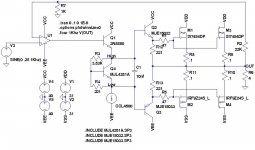
Low output current of LM4702 amplifier is obstacle when you wont to drive more than one pair of MOSFET transistors because they have quite high gate capacitance. In target amplifier PCB signal tracks should be as short as it's possible and the same length for both channels (to keep THD + noise low).
Low output current of LM4702 amplifier is obstacle when you wont to drive more than one pair of MOSFET transistors because they have quite high gate capacitance. In target amplifier PCB signal tracks should be as short as it's possible and the same length for both channels (to keep THD + noise low).
Hi Veteran
What was your impressions using the Lateral output MOSFETs
(It was the 2sK1058 and its complement wasn't it that was used?)
Given that the the LM4702 has a 5ma Source/Sink limitation.
Although I see on the data sheet its max is 10ma.
Have you done any frequency response tests above 40khz
Forgive me if I haven't read all of this thread, I may be going over old ground.
I first used the 2SK1530 and 2SJ201 devices back in 1993 when they were first released, In a 800 watt amplifier I designed.
A most excellent device, they just got
way to expensive for my taste.
They aren't to expensive - I just ordered them for about 4$ for 2SK1530 and 6$ for 2SJ201 (I'm using such pair). It's hard to buy something else (with low GTV). I didn't had chance to measure this amplifier response for > 20kHz but I think that we can have there some THD+N rise.
This amp is quite transparent and powerful even when only one output pair is used (supply voltage range is wide).
This amp is quite transparent and powerful even when only one output pair is used (supply voltage range is wide).
questions about output stage and compensation
Veteran,
Thanks for your pioneering work on this new part! and great job on the schematic! I want to try one of these babies as I know the low bias (20ma?) on most chip amps output stage is limiting their transparency. I found that at least 200ma through a pair of mosfets is needed to make them sing.
Questions:
Why do you need a transistor to bias the mosfets?..cannot you just use a pot to set the bias then substitute a fixed resistor?...this is what I did in my old mosfet amp years ago....
Also why the .22 ohm source resistors.....what purpose do they serve....other than to add resistance and their sound? Again, my old mosfet amp had no source resistors.
How about the output coil and zobel....are they really necessary for driving a cone speaker and normal speaker wire? How does the amp look on the scope into an 8 ohm load with no capacitance and then how does it look with various amounts of capacitance?.......again, my old mosfet amp had no inductor on the output but I did have a zobel, even though I was driving simple 8 ohm speakers....would like to experiment now....many people say zobels in the amp mess with the sound.
I suppose the 12 v zeners are for protection?
How about the capacitance you added shunting the input and across the feedback cap (listening tests?). How did you arrive at those values? Did you listen to the amp without the shunt cap? Does the square wave look better with the cap across the feedback resistor?
As you can see I am a minimalist....usually less parts = better sound.
Thanks,
Ric Schultz
was your old amp capacitatively coupled?
minimalist isn't quite going to work with the LM4702 -- the best results were found with the design in the National Semi application notes -- if you want to do minimizing I suggest omitting the blocking capacitor on the input, but make darned sure that there is little or no DC on the output.
minimalist isn't quite going to work with the LM4702 -- the best results were found with the design in the National Semi application notes -- if you want to do minimizing I suggest omitting the blocking capacitor on the input, but make darned sure that there is little or no DC on the output.
The Saint said:...Given that the the LM4702 has a 5ma Source/Sink limitation.
Although I see on the data sheet its max is 10ma....
The source/sink "output" pins have a limited current flow capability, just like any op-amp chip. This current limit varies from chip to chip due to manufacturing tolerances. The spec sheet says this can vary from 3 mA to 10 mA, with 5.5 mA being a typical figure. I have measured the sink limit at 4mA on one sample which I have permanently on a breadboard for doing such tests. It varies slightly with the power supply voltage. The source pin seems to be able to "source" more current than 10 mA, but I haven't pushed it to destruction.
The current has to drive the output devices and the Vbe multiplier. At high frequencies the capacitive load becomes significant too. I think that designs should assume that no more than 3 mA of drive current is available. ie. the output stage should have a current gain of a few thousand and the Vbe multiplier should operate at 1 mA or less.
The old amp was completely DC....it had differential fets on the input to keep it from drifting too much....no cap in feedback either. It was a highly modified version of the Borbely 60 watt circuit that was published in Audio Amateur years ago. I could not figure how to do a pic of the schematic here so I loaded it on my website along with the original schematic. If you go to http://www.tweakaudio.com then to products, then to free tweaks, then to electronic tweaks....and go to the very very bottom of the page you will see a tiny gold button....push there for schematics. You can see I added fets to the front end and removed much stuff...all to make it better sounding (which it did).
This was long before I had a computer, so please excuse the messy quickly hand drawn circuit.
This was long before I had a computer, so please excuse the messy quickly hand drawn circuit.
Has anyone experienced instability with their LM4702 amp? I am measuring high frequency oscillations at the peaks of sine waves when driving a 4 ohm test load. The oscillation frequency seems to be about 6-7Mhz. Any suggestions???
try inserting say 10-47 Ohm Base resistors in each output transistor, the value will depend on the gain of the o/p devices
This is assuming you are using Bipolars in the o/p stage.
MOSFETs in this circuit are another story all together... 😀
This is assuming you are using Bipolars in the o/p stage.
MOSFETs in this circuit are another story all together... 😀
Yep, using bi-polars. I have tried base resistors but to no effect. I also notice oscillations at a much lower amplitude without the output stage connected at all.
I am only using one side of the chip for a monoblock amplifier. The other side I have tied the source to the -VE input with 10K and I have tied the +VE input to ground via 10K. Has anyone else had any success only using one channel?
I have been working on this for 3 days solid and cant seem to fix the damm oscillations. If everyone else has not had similar problems, I must be doing something wrong, just cant work out what...
-Stuart.
I had oscillation when I used the Sanken devices and I think it was entirely due to poor layout (well, not really poor, but not optimal.)
In the second batch I built with lateral MOSFETs there have been no oscillatory problems -- in this version I followed the layout more closely, used silver mikes in the compensation, polypropylene bypass caps.
That's why I said earlier that this isn't a "minimalist-friendly" chip.
In the second batch I built with lateral MOSFETs there have been no oscillatory problems -- in this version I followed the layout more closely, used silver mikes in the compensation, polypropylene bypass caps.
That's why I said earlier that this isn't a "minimalist-friendly" chip.
I agree with Jackinnj - the are no problems when using FET output stage.
Ric Schultz
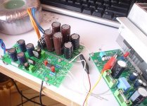
I'm running my output transistors 110mA per channel (they have low threshold voltage so this is possible). VBE transistor is a useful thing when using small heatsink.
Like you can see my boards is quite universal and there is no need to use all the components (no output coil in my present amp).
This amplifier needs preamp 😀 Now it sings 😀
Ric Schultz
I'm running my output transistors 110mA per channel (they have low threshold voltage so this is possible). VBE transistor is a useful thing when using small heatsink.
Like you can see my boards is quite universal and there is no need to use all the components (no output coil in my present amp).
This amplifier needs preamp 😀 Now it sings 😀
Attachments
As simple dual opamp?
Just wondering, is there any reason you could not simply tie the "sink" and "source" pins together and use the 4702 as a high voltage opamp? I know it can only do about 4-6ma, but I was just wondering if it would work. It seems thats what the test circuit shows in the datasheet. But I was not sure what the implication are.
Any thoughts?
- Status
- Not open for further replies.
- Home
- Amplifiers
- Chip Amps
- Lm4702