You have to use low Gts transistors. With IRFP240 and IRFP9240 your amplifier will work more in class B than A A/B 😉
veteran said:You have to use low Gts transistors. With IRFP240 and IRFP9240 your amplifier will work more in class B than A A/B 😉
AndrewT said:Hi,
what is a low Gts transistor?
Which parameter do I read?
Why is low Gts necessary?
Low Vgs is not at all necessary. 🙂
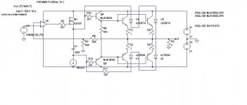
You just have to use the LM4702 as an opamp (tie the source and sink together) then drive your output stage with something like a BS107(small signal MOSFET) in common drain which will present a very easy load for the 4702. You can then use a VBE multiplier, or diodes + pot, or whatever other means of obtaining your bias voltage/current you like. This approach allows you to almost limitless output device possibilities.
I have been running a couple circuits now with this approach with very good success.
This link describes the output stage I am currently using:
http://www.diyaudio.com/forums/showthread.php?postid=1105232#post1105232
I just made a PCB with no input stage and drove the circuit with an LM4702. I now have two channels running, and they sound great.
I have found that using the LM4702 in this way seems (to me anyway) to get more out of it. I was not very impressed with either the data sheet application nor the later app note circuit, but that may just be me.
Here is what I will try next which I think will be better than using Darlingtons like SAP16...
Cheers!
Russ
Attachments
Here's a comparison -- I use a Sumo Polaris in the lab -- so I thought I would compare them from 10kHz to 100kHz --
An externally hosted image should be here but it was not working when we last tested it.
Questions
Hi, working on my LM4702.
Questions-
1. What darlingtons have people in the USA been using? (other than the Sankens, I cannot get my hands on any of those fancy schmancy Sanken SAP16N and SAP16Ps here in the USA, and even if I could, wondering what else would be ok to use).
2. Can the LM4702 drive 2 pairs of darlingtons per channel rather than the single pair I have been seeing on this thread?
3. If I use the Vbe multiplier, will this help provide drive current to the darlington pairs, making it possible to parallel some more output devices?
4. For a BJT amp, what are people using or suggesting for the Vbe multiplier xistor?
- thanks
I have used the On Semi and Texas Instruments Darlingtons -- paralleling Darlingtons isn't generally recommended.
The Sanken devices have been obsoleted and are replaced with a "somehwat" similar device -- Perfusion in the UK has the new devices listed. I found that their service was very good when I ordered some of the SAP devices from them about a year ago.
The Sanken devices have been obsoleted and are replaced with a "somehwat" similar device -- Perfusion in the UK has the new devices listed. I found that their service was very good when I ordered some of the SAP devices from them about a year ago.
Hi,
use the 4702 to drive discrete darlingtons arranged in dual EF.
You can tack on as many output devices as the driver EFs will allow.
That's the beauty of discrete design.
Integrated darlingtons usually perform worse than discrete. I suggest you forget they even exist.
use the 4702 to drive discrete darlingtons arranged in dual EF.
You can tack on as many output devices as the driver EFs will allow.
That's the beauty of discrete design.
Integrated darlingtons usually perform worse than discrete. I suggest you forget they even exist.
Man, this is making me wish I had more free time to get my output stage finalized. . . . .
Crud. 🙁
I guess I will have to wait until the summer after teaching responsibilities end. . . . .
Crud. 🙁
I guess I will have to wait until the summer after teaching responsibilities end. . . . .
AndrewT said:Hi,
use the 4702 to drive discrete darlingtons arranged in dual EF.
You can tack on as many output devices as the driver EFs will allow.
That's the beauty of discrete design.
Integrated darlingtons usually perform worse than discrete. I suggest you forget they even exist.
Complementary Darlington a la Leach, perhaps:
An externally hosted image should be here but it was not working when we last tested it.
Dr. Leach places diodes for the VBE multiplier on the heatsink -- I may be able to adapt my driver boards to do this.
Without doing the math, how much current will this draw? The 5 mA is a pretty limiting factor. . . . .
Hi Jacki,
where did that schematic come from?
The nfb tapping is off the wrong side of the inductor.
where did that schematic come from?
The nfb tapping is off the wrong side of the inductor.
The typical output current of the LM4702 should be around 5.5 mA. It's in the data sheet.AndrewT said:Hi Dfdye,
what 5mA limit?
My concern is that the Leach output stage will draw more current than the chip is capable of putting out. I haven't done the math, so I don't know, but I would check before I put the time and effort into building an output stage that wouldn't have a chance of working. I just don't know!
I would love it if it will work, but the idea that Russ came up with for using mosfets as the first current gain stage of the "darlington" (not that his stage resembled anything close to a Darlington configuration) sounds like a great idea. Hfe seems to be around the right range, but I haven't thought about it in a while.
Hi Df,
let's do the sums you cannot be bothered to do.
Assume the amp will deliver 100W into 8ohms. that's equivalent to 40Vpk.
Let's also assume the speaker Re=6r0, the peak current will be 6.67Apk.
The current gain of the EF output pair will need to exceed 1212 (6667/5.5)
Now choose devices that meet this requirement.
Driver hFE >50 Output hFE> 30 overall gain >1500.
With modern high gain devices 8000 is achievable.
Add a pre-driver and 100,000 from low gain devices is on, over a million from higher gain devices.
Most darlington transistors and 2xtransistor darlingnton connections with B-E resistors have a turn-on current which must be exceeded before the large Hfe (d Ic/d Ib) takes effect. Up to about 1 Amp the current gain can be far from linear. The current gain also droops at high currents.
Also, the LM4702 output current needs to drive the input capacitance of the following stage, so the drive requirements for higher powers increases with frequency.
BTW: I have a LM4702 amp with a TIP142/147 pair or darlingtons in the output stage with +/-40V rails. I know they are old devices, but it sounds quite good.
glennb said:
BTW: I have a LM4702 amp with a TIP142/147 pair or darlingtons in the output stage with +/-40V rails. I know they are old devices, but it sounds quite good.
Those were the first devices I used, then the SAP devices, and now the lateral MOSFETs. I was able to attain the best "numeric performance" with lateral MOSFET's but will let the matter of best sonics reside with the constructor.
...but the idea that Russ came up with for using mosfets as the first current gain stage of the "darlington" (not that his stage resembled anything close to a Darlington configuration) sounds like a great idea.[/B]
I can say I have been very happy with it. 🙂 Keep in mind I am not using it at all conventionally. The circuit shown here:
http://www.diyaudio.com/forums/attachment.php?s=&postid=1118401&stamp=1169995045
is only half the amp. 🙂 It is being driven fully symmetrically via one of my TXD modules. The output is bridged. I must confess I cannot (at least not accurately yet) measure the distortion, but I can report it sounds great, and it can drive a serious load (3-4 ohm) without fear. The on-device biasing diodes work wonderfully.
I am finding using the 4702 as an ordinary op amp(tie sink/src) seems to be getting me the results I like the best so far.
I have tried SAP15/16, TIP, (yes discrete too) etc in conventional way, and I liked it fine, but I like this better.
I also have a newer pseudo-quasi-complementary (there is some debate on what to call it) FET output stage which is showing a lot of promise. Still my favorite is the one you mention. BTW that BS107 works fine, but so will many other transistors.
Cheers!
Russ
😀AndrewT said:Hi Df,
let's do the sums you cannot be bothered to do.
The last time I did this math for a similar system, I was assuming closer to the limits of the chip, IE 65V rails. The devices I had in mind were stretched to their limits under these circumstances.
Andrew, you seem to have a different perspective than me, so I will deffer to you: what devices would you recommend trying in the Leach output for 65V rails?
- Status
- Not open for further replies.
- Home
- Amplifiers
- Chip Amps
- Lm4702