Men at work Complementary Darlington hooked up to my LM4702 driver board -- needs a lot of work yet:
An externally hosted image should be here but it was not working when we last tested it.
LM4702 and Vertical MOSFETs
Borbely used a totem VBE multiplier in his "Big Muscle" article -- (Audio Amateur 3/1993) -- so you can drive IRFP's etc -- details omitted to protect the innocent: -- but you have to fit R1,R2,R3,R6 for the bias you need:
Borbely used a totem VBE multiplier in his "Big Muscle" article -- (Audio Amateur 3/1993) -- so you can drive IRFP's etc -- details omitted to protect the innocent: -- but you have to fit R1,R2,R3,R6 for the bias you need:
An externally hosted image should be here but it was not working when we last tested it.
The problem with the LM4702 is that the voltage between the Sink and Source pins is limited to 6-7V. I have gotten as much as 6.7V between the pins but I haven't tried something like this. Still, I don't see how I can get more voltage since it seems to be a limitation of the LM4702. Thanks for the circuit.
-SL
-SL
Lama, I honestly don't know what you are talking about. I get full voltage swings out of my chips both with the sink and source independent and tied together.
If you can't get full +/- 65V out of these chips, there is more than likely something wrong with your chip! I can't immediately think why you would only be getting 6-7V. Could you post a schematic of your setup or testing system?
-----PS You aren't talking about 6-7 mA of CURRENT are you??
If you can't get full +/- 65V out of these chips, there is more than likely something wrong with your chip! I can't immediately think why you would only be getting 6-7V. Could you post a schematic of your setup or testing system?
-----PS You aren't talking about 6-7 mA of CURRENT are you??
No, the lama is correct -- you need -- he's talking about the voltage needed to bias the output devices -- use a constant current of 1 mA and drive the top end of the VBE multiplier and you'll see what he means.
🙄jackinnj said:No, the lama is correct -- you need -- he's talking about the voltage needed to bias the output devices
Duh. Of course I am an idiot.
Now we are all on the same page. I thought you were talking about output voltage, not bias voltage. My bad.
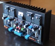
Looks very nice, Monkey. Any other specs. available, like supply voltage, THD+N, etc, etc? The driver ICs, I only see one driver per channel, are these for biasing or for higher driver current? Just curious. Thanks for the nice pic.
-SL
-SL
Hi,
it's a 2pair output stage with complementary drivers for the upper and lower halves.
Neat, though.🙂
Note,
no mention of any darlingtons in his device listing.
it's a 2pair output stage with complementary drivers for the upper and lower halves.
Neat, though.🙂
Note,
no mention of any darlingtons in his device listing.
Photo shows LM4702+2SA1943/2SC5200, drivers: 2SA1930/2SC5171 are mounted to the HS through the square holes in the PCB
Have a look at monkey29’s web site for more photos.
Great OEM work.
Have a look at monkey29’s web site for more photos.
Great OEM work.
I see now, didn't see those holes before. The web site also had some more pics, as mentinoed, that made it more clear. Thanks.
-SL
-SL
I am not able to design it ....and I don't know if it could be done 😕 but
Could it be a good idea to use some DELTA OB-2A Power Amplifier Output Boards the after the LM4702 ?
http://www.delta-audio.com/OB-2A.htm
...just asking the pros....
Could it be a good idea to use some DELTA OB-2A Power Amplifier Output Boards the after the LM4702 ?
http://www.delta-audio.com/OB-2A.htm
...just asking the pros....
To run those boards with a LM4702 you will need an intermediate driver stage. The LM4702 only has about 5mA of output current so not enough to directly drive a BJT output stage unless not planning on much output current. If you used FETs on those boards (possible since the space is there for a gate resistor) then you would still need a driver stage to get good slew rate (>15V/us) and the extra current would be very helpful for driving 3 devices in parallel.
Don't get too stuck on the LM4702. It is a great part but National has mono version coming very soon that have much higher current drive that may eliminate the need for a driver stage for some designs. The new parts probably won't eliminate the driver stage for a 3 device ouptut stage. You would want the current gain to run high power. Granted, you don't have to stuff those boards with 3 devices, could use just one or two. Then if FETs you could drive them pretty good without a driver stage for power ranges in the 100W - 150W area.
-SL
SpittinLLama said:To run those boards with a LM4702 you will need an intermediate driver stage.
You also need to bias the transistors with a VBE multiplier --
SpittinLLama said:Don't get too stuck on the LM4702. It is a great part but National has mono version coming very soon that have much higher current drive that may eliminate the need for a driver stage for some designs. The new parts probably won't eliminate the driver stage for a 3 device ouptut stage. You would want the current gain to run high power. Granted, you don't have to stuff those boards with 3 devices, could use just one or two. Then if FETs you could drive them pretty good without a driver stage for power ranges in the 100W - 150W area.
-SL
When?! Routing of such board will be much easier than stereo version 😉
opps, forgot about the bias stage too. Soon, Veteran, soon. . . weeks for some, months for others, countable on one hand.
-SL
-SL
Re: LM4702+MOSFET / Bipolar Transistor
At one time I had mounted the LM4702 on the same heatsink as the output transistors -- and the distortion was an order of magnitude higher than when the LM4702 was heatsinked on its own.
It does not like to get hot -- Doug Self has a few paragraphs in his book discussing thermal distortion --
monkey29 said:LM4702 AMP Module...
LM4702+2SJ201/2SK1530 (MOSFET )
driver: 2SA1930/2SC5171
LM4702+2SA1943/2SC5200 (Bipolar Transistor)
driver: 2SA1930/2SC5171
At one time I had mounted the LM4702 on the same heatsink as the output transistors -- and the distortion was an order of magnitude higher than when the LM4702 was heatsinked on its own.
It does not like to get hot -- Doug Self has a few paragraphs in his book discussing thermal distortion --
Hi all,
I have a spare LM4702B and some 2SK1058/2SJ162 pairs and dont know what will I do with them. Until yesterday!
I found a circuit schematics somwhere that;
Do you think it works fine?
PS: On output you see 10E resistors. However theyre coils not resistors.
I have a spare LM4702B and some 2SK1058/2SJ162 pairs and dont know what will I do with them. Until yesterday!
I found a circuit schematics somwhere that;
An externally hosted image should be here but it was not working when we last tested it.
Do you think it works fine?
PS: On output you see 10E resistors. However theyre coils not resistors.
Dxvideo said:
Do you think it works fine?
PS: On output you see 10E resistors. However theyre coils not resistors.
You might want to make the biasing resistor variable so that you can adjust the idle current. I would think that the source and sink pins want some measure of a.c. coupling -- usually there is capacitor across the VBE multiplier -- i have used 100nF -- note also that the nat semi designs usually show higher gain than would be derived from your schematic.
Try it and let us know.
Jack
- Status
- Not open for further replies.
- Home
- Amplifiers
- Chip Amps
- Lm4702