If you can't understand it is a concept that is just fine.
You haven't listened to it and tested it, period. Still the sound quality is the main factor regardless what simulations say and measurements. If it is not done to your criteria then just don't try it. I am not forcing you to.
All these posts and I didn't get any good advice from you regarding PCB, just negative words.
Just saying since you do professional layout in audio.
Best Regards,
Aleš
You haven't listened to it and tested it, period. Still the sound quality is the main factor regardless what simulations say and measurements. If it is not done to your criteria then just don't try it. I am not forcing you to.
What is commercial and what is professional audio for you?I... I do very little commercial audio work, and don't really need to look at NAIM audio...
I do layout for professional audio...
All these posts and I didn't get any good advice from you regarding PCB, just negative words.
Just saying since you do professional layout in audio.
Best Regards,
Aleš
H.Ott makes this very clear.
The joints must be electrically conducting to make the screening effective.
He describes solutions with gaskets.
Open up any TV box, be it decoder or recorder, or display. They all have a "tuner" unit.
look at the way they assemble these little screening boxes.
I opened an old mobile phone recently to find many screening boxes with tiny circuits inside.
One screening box had a few components AND another screening box inside.
I managed to open the inner box to reveal more tiny components.
All these screening boxes were soldered around their perimeters to the multi-layer PCB plane.
What do you mean I cant understand a concept....
I have tried it and many more methods of routing the 0Vs on many types of PCB over the last 30 years, I know what works, I understand the problems of RF pollution we have these days...
Signal integrity is critical in any design...that's what sound quality is based on.
Back to measurements bad I see.
Commercial audio is stuff like Naim, etc professional is what you get in studios, on tour etc or communications equipement, sensitive analogue might be a phase array sonar.
We moved from audio frequency to 1Ghz range...
Studio equipment is, at least to my ears, very analytical in sound and therefore hard to listen any enjoy to music for longer periods....
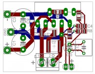
@marce: What do you think about this mono PCB? Of course you might again say it has spider legs, but in reality traces are shorter than they would be if GND lines would be connected through other components, referring to C4 and R8.
C1 and C3 are 100uF/50V but this module is supposed to be power with regulated PSU, dual mono design. R9, feedback resistor, is placed on the bottom and might interfere with Vcc and Vss, so placing through hole resistor directly on the LM3886 pins is not excluded.
BR,
Aleš
Studio equipment is, at least to my ears, very analytical in sound and therefore hard to listen any enjoy to music for longer periods....
@marce: What do you think about this mono PCB? Of course you might again say it has spider legs, but in reality traces are shorter than they would be if GND lines would be connected through other components, referring to C4 and R8.
C1 and C3 are 100uF/50V but this module is supposed to be power with regulated PSU, dual mono design. R9, feedback resistor, is placed on the bottom and might interfere with Vcc and Vss, so placing through hole resistor directly on the LM3886 pins is not excluded.
BR,
Aleš
Attachments
Nice...
On RF you do have to cater for it these days. I would not have separated the return for C4 R8 as they are closely related components in the circuitry and having them at the same GND would be better for circuit operation IMO, you are reducing the parasitics between the two device. This is what I meant when I was ranting about the spiders legs GNDs, I do believe you can go to far, and related components would be better with a nice solid trace to the star point from both devices.
I did not explain myself very well earlier, my apologies.
I opened an old mobile phone recently to find many screening boxes with tiny circuits inside.
One screening box had a few components AND another screening box inside.
I managed to open the inner box to reveal more tiny components.
All these screening boxes were soldered around their perimeters to the multi-layer PCB plane.
Base stations were more fun as castings or machined from solid everywhere. The biggest nightmare in early mobiles was the connection for the external antenna on the car kit. everyone was happy when that was dropped.
Power feedthroughs could be used for audio so you could place circuits in those nice die cast boxes, but audio feedthroughts are more tricky to find a solution that filters AND ticks audiophile boxes for bling...
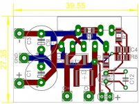
I do not now much about 3886 but this PCB looks already a lot better.
With some minor tweaks it could be excellent.
For example:
- Turn the output socket around so that the gnd terminal will be on the left side (closer to the power ground = shorter track).
- The chips GND pin has negligible current in it and has nothing to do with the power ground nor with the input ground. I would keep it away from the input ground but thats just me...
- As Marce suggested with the C4,R8,R10, do it. I would also include the R7 in that order...
- R9 might have a better place below the bottom pin row of the chip. Other input circuitry might want to be moved closer to this component (as we now should have space for them when the speaker connector has turned...
IMHO
Last edited:
You are clearly mistaken, PCB has excelent grounding because every components ground is routed into star point.
Which is exactly what you do not want. You want a low impedance ground, because this minimizes the error voltage that develops across the ground connections. This means a ground plane... Where you connect the feedback ground and input ground also matters greatly. I suggest connecting the at the output connector. You can find more detail here: http://www.diyaudio.com/forums/chip-amps/252436-lm3886-pcb-vs-point-point-data.html You can also see the impact of a poor layout vs a good one.
Please do the math on the feedback resistors. The 1 kOhm feedback resistor will dissipate 392 mW if the amp is operating with a full swing on a +/-28 V supply. 613 mW for a +/-35 V supply. Your 1206 components are probably rated at 125 mW or 250 mW at the most.
For the questions surrounding the decoupling, I suggest taking a look at my Taming the LM3886 website: Taming the LM3886 Chip Amplifier
~Tom
I have NEVER got a chassis enclosed amplifier quieter than a bare prototype on.
Intersting. Good. Thanks!
//
I am so glad someone agrees with my views on ground planes and analogue. As stated earlier even though I have 30+ years experience of layout and work on some very cutting edge designs, I get shot down on DIY audio quite often for my viewpoints, yet provide training and do on site design for critical projects for top end aerospace/mil/medical where they listen to me!!!!!!!
This is why I very rarely get involved with trying to give advice here these days🙂
This is why I very rarely get involved with trying to give advice here these days🙂
I have NEVER got a chassis enclosed amplifier quieter than a bare prototype on the test bench.
I have NEVER got a two channel amplifier quieter than a Monoblock.
Then you maybe need to re-think some of the things you do, they should be as quiet. I know we do disagree on a lot of grounding schemes, I would be interested in the schemes you have tried.
My problem at the moment though is gear, just moved house and discovered a box is missing!!! containing a scope, sig. gen. and other test equipment. Previous landlord is a **** and has claimed he's binned anything that was left, has not forwarded any mail and generally made life hard.
I am so glad someone agrees with my views on ground planes and analogue. As stated earlier even though I have 30+ years experience of layout and work on some very cutting edge designs, I get shot down on DIY audio quite often for my viewpoints, yet provide training and do on site design for critical projects for top end aerospace/mil/medical where they listen to me!!!!!!!
This is why I very rarely get involved with trying to give advice here these days🙂
Something about being able to lead the horse to water but not being able to get him to drink. Yeah... 🙂
You never see the giant spider star grounds in professional gear of any sort. The reason is simple: The giant ground spider doesn't provide as good performance.
~Tom
I have said this many times, it is a corruption of GND star points (taken to the extreme), where one or more ground planes join together. What I do try to get across is that especially in todays RF polluted environment they can act as a broadband antenna, and often look very similar to such antennas I have laid out.
🙂
🙂
I do not like ground plane because you can not be the judge which is the line of least resistance and where they are going currents. In star-connection you determine the reference ground and amplifier is completely silent. If the pcb has a ground plane I was cut to tape is that I would define the flow of current trends and interference. As for shielding often happens that grounding entered interference in shield and it acts as an antenna. I grounded housing with network - mains grounding through the filters and signal ground via a resistor and never had even a little ripple even at MC preamplifier and with unconnected input
Last edited:
Of course you can control currents...Ask yourself why does the extreme spiders leg type ground routing only appear in DIY audio and not in other analogue designs (including pro-audio and very sensitive analogue). You can still separate grounds and have starpoints, this is often done, I mean the spindly legs where often every component has a thin high inductance track to some arbitrary starpoint.
At this point maybe we should look at how signals flow, and why audio can be so prone to ground loops (often created because many don't understand the return current mechanism). Firstly electrons do not whiz round the circuit like carriages of a train , they meander and drift slowly a few fractions of a mm every second or so. At DC return paths follow the path of least resistance, as the frequency increases this changes from path of least resistance to path of least inductance. So you have to cater for this when covering 20-20000Hz, then there is the possibility of RF interference, then there are the decoupling loops creating local loops etc etc...
At this point maybe we should look at how signals flow, and why audio can be so prone to ground loops (often created because many don't understand the return current mechanism). Firstly electrons do not whiz round the circuit like carriages of a train , they meander and drift slowly a few fractions of a mm every second or so. At DC return paths follow the path of least resistance, as the frequency increases this changes from path of least resistance to path of least inductance. So you have to cater for this when covering 20-20000Hz, then there is the possibility of RF interference, then there are the decoupling loops creating local loops etc etc...
Are you saying that if you have two parallel conductors, one of 0.1 ohm and one of 0.2 ohm that all the current will flow through the conductor with the lowest resistance?
What are you on about, I have said no such thing read what I have said... I have said that DC/low frequency return currents follow the path of least resistance and as the frequency increases this return current path changes towards the path of least inductance.
Where did I say what you are stating and how can you infer that from what I wrote!
Where did I say what you are stating and how can you infer that from what I wrote!
- Status
- Not open for further replies.
- Home
- Amplifiers
- Chip Amps
- LM3886 with SMD components