99.9999999 % (if not more) of the heat is conducted through the back of the package. Is it really worth the last 0.0000001 % ...
I can't resist to don't reply 🙂
More I read, more and more new things I "learned" from you …
By Your extraordinary experience and knowledge, if we "pump" for example 50W of power into IC, 49.99999W of heat will go out to back side and less then 50nW or as you like to "play" with large numbers because you know math and physics better then anyone else here, 50.000pW (pico Watts) on front side! 😱
Congratulations, you discovered new thermal-insulating materials!
Thats how "Engineering :: Done :: Right"!
Now I don't believe ANY numbers you presented here, including those from your signature! That's all a very nice marketing campaign to sell your's PCB made of platinum and diamond dust for "just" xy$ …
Those fairy tales for kids talks to someone else …
@Yu3ma : Please don't mix trolling and ignorance, it really doesn't help give your PCB layouts any credibility. Tom owns an Audio Precision, I think it is safe to say he can do better measurements than almost anyone on this forum. He also designs ICs so understands how they are assembled better than most.
When someone presents a calculation and you disagree then the correct approach is to present some calculations or data to back up your point. Resorting to attacking the poster really does show that you don't understand but think that making noise will somehow win you the argument. Tip of the day: It won't.
When someone presents a calculation and you disagree then the correct approach is to present some calculations or data to back up your point. Resorting to attacking the poster really does show that you don't understand but think that making noise will somehow win you the argument. Tip of the day: It won't.
why dont you present some calculation to back up your point? or data maybe ? go test this yourself then tell what you think
Because I am happy that Tom's data as presented is correct. I am not trying to dismiss his calculations. yu3ma and you are so the onus is on you to prove your point.
On packages like TQFP a heatsink can allow the chip to dissipate a few watts...
Thermal conductivities W/m.K
Copper : 380 ~ 400
Alu : 200 ~ 250
Silicon chip : 149
Epoxy Chip moulding compound 0.5 - 1
Thermal conductivities W/m.K
Copper : 380 ~ 400
Alu : 200 ~ 250
Silicon chip : 149
Epoxy Chip moulding compound 0.5 - 1
I would suggest that a 1Vac continuous sinewave test signal @ ~50Hz into 4r0 dummy load would turn on the thermal limiting quite quickly, maybe within 1minute, or 10minutes, or 60minutes.@tomchr
if lm3886 can output 6,7v at 50hz continous sine(not that averaged thing of yours), to speaker of 4 ohms ,without turning on spike and running at that output for full hour from +-12v psu, could you calculate how much heat is being transfered from chip to heatsink of dimensions 94mm *72mm *3mm , that same heatsink being mounted on front side of lm , and somehow prove to me and everyone else that it is worthless as you say it is.
as i am feeling good today i would like to propose a test,if you would like i will mount lm facing front to some huge heatsink i have available(better say water cooling with 240mm radiator) and connect it on better power supply to try to pull more power out of front side of chip than your comercial design can pull out of back of lm (but not "with vanishingly low THD and phenomenal sound quality" just as far as it goes without spike.).but that will i do only if you would be nice and actualy try this you call "new" mounting method for yourself and maybe measure whatever you measure to feel fine.
You won't need 6.7Vac to prove that fixing the device back to front does not work !
and then you take account of the relative thicknesses.On packages like TQFP a heatsink can allow the chip to dissipate a few watts...
Thermal conductivities W/m.K
Copper : 380 ~ 400
Alu : 200 ~ 250
Silicon chip : 149
Epoxy Chip moulding compound 0.5 - 1
Tom's estimate of 0.00...% was probably close enough to completely refute the stupid idea of back to front heatsinking.
I would suggest that a 1Vac continuous sinewave test signal @ ~50Hz into 4r0 dummy load would turn on the thermal limiting quite quickly, maybe within 1minute, or 10minutes, or 60minutes.
You won't need 6.7Vac to prove that fixing the device back to front does not work !
Do you suggest to test with resistor is better than with speaker,will try that latter no matter what results are ,i just hope to see first hand what wil happen .
Yeah it's probably 99.9% instead of 99.9999999 % but I think that makes the point.
Also, stuff like TQFPs have a very thin layer of epoxy molding compound above the die (so if you stick a heatsink on it, it kind of works) ; however LM3886 has a much thicker layer of epoxy (a few mm, like TO-220 power semiconductors and the like) ...
Also, stuff like TQFPs have a very thin layer of epoxy molding compound above the die (so if you stick a heatsink on it, it kind of works) ; however LM3886 has a much thicker layer of epoxy (a few mm, like TO-220 power semiconductors and the like) ...
A resistor as a dummy load is easy for others to replicate your work and get the same results, if you have done it correctly.
The second advantage to using a resistor as a dummy load, is that the "stress" on the components is much less than when using reactive loads.
You are less likely to "blow up" your precious prototype using a resistor load, than when using a speaker load.
Thirdly, a speaker is a very variable load, is the version one of your KEF xxxb the same as your neighbours version 17 of the same speaker.
This applies all the way across every manufacturer's range of speakers. They change the specifications. A speaker that sells for ten years may well go through five generations of changes. If it was of Japanese origin it may well go through those 5generations in little over a year and then they give it a completely new model name to try and sell to all the gullible buyers who have version 3.26
Yes. But it needs elaboration.I was just talking with a manufacturer about heat dissipation of aluminum and copper, they mentioned that copper conducts heat better but aluminum dissipates heat better, is there any truth to that?
Copper has a better heat conductivity, and a specific heat capacity. As such, the velocity that the heat will take through the bulk material will be some value.
Aluminum has a lower heat conductivity, but it's heat capacity is quite a bit less than copper. So heat will travel faster through the aluminum.
If you compared two long rods, one of aluminum, one of copper...hold onto one end, and blast the other with a torch.... you will find that you have to let go of the aluminum first.
But in the end, the copper will transfer more heat..
The parametric being discussed is called "diffusivity".
Interesting, thank you for the information. The datasheet is very shy on actual information regarding the heat paths, so I'll have to do more research to figure out exactly what they are selling.Some packages can be cooled from both sides :
IRF6718L2TRPBF International Rectifier | IRF6718L2TRPBFTR-ND | DigiKey
In this case, the top side is metal (not resin as LM3886), and the bottom is connected to thermal vias and perhaps a heat sink on the other side of the pcb (or just the ground plane)...
when you do know physics like everyone seems to know on this forum , could you please make it clear to me how could i calculate how much dissipation there realy is from front side of chip ,could i use some ntc thermistors for temp measurments and how to translate resistance change to degrees change. and how to get some actualy real measurments out of that all. i dont care if in end it equals to 1w dissipation out of front side but i want to test it .
You'd have to measure the difference in heat flux through the top and bottom paths. That is very difficult to do accurately, as the instrumentation is generally beyond the DIY'er.
In the previous test technique (by yu3ma) of using ice water and partial immersion, I do not see how that can provide accurate results. The water is being heated by a constant power source, and does not care what the temperature of the chip is. Within the first 5 or 10 seconds of using that method, it will become impossible to discern the actual heat transfer coefficient.
jn
@Toni.
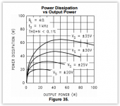
If you are able to output 6,7V RMS to a 4 ohm resistive load (not a speaker) that equals 11W of output power. There is no data on power dissipation in the datasheet for +-12V, but we can do an approximation from figure 35. (Attached). I am guessing that with 10W output power that the dissipated power is in the 5W to 10W range.
If the LM3886 can dissipate 7,5W power through the plastic to a heat sinc without hitting shutdown or activate spike protection we can calculate the thermal resistance assuming heat sink temperature is stable @ 45 degrees celcius.
Shutdown occurs at 155 degrees.
That is 110 degrees with a dissipated power of 7,5W. Thermal resistance is then 110/7,5= 15C/W.
Compared to the 1C/W through the "normal" way that is considerable worse and will add little to the total thermal performance.
Assuming no loss from the top-side clamp to the heat sink the total thermal resistance will be: 1/(1/1)+(1/15)) = 0,94C/W.
So in theory there *is* a little gain, but in my calculations there is a lot of "if's" and assumptions, so some real data would have been nice.
Anything in the range of 0,94 to 0,99 could be true.
Attachments
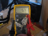
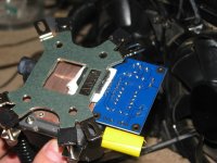
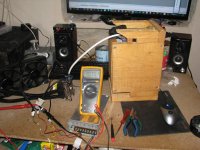
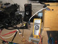
wow armand thank you for calculating that and making it simple to understand, as i promised before i put lm facing front to cpu water cooling and at resistor of 5,7ohms i measured 10Vac but this time at rails of +-38.5V and as i took picture thermal protection kicked in , some 15-20 seconds after i turned on the 50hz signal. later with same 4ohms speaker from before i measured 13Vac but that lasted just little over 10 seconds when thermal protection kicked in again. maybe i overdid it with 38V rails . be it 5 watts from front side or less, i am happy to know that is possible to push this fine chip little bit more, and to finaly see that thermal protection in action,it seems to work fine😀
Attachments
Ok, lets cool down a bit, clear some stuff and continue to talk "normally".
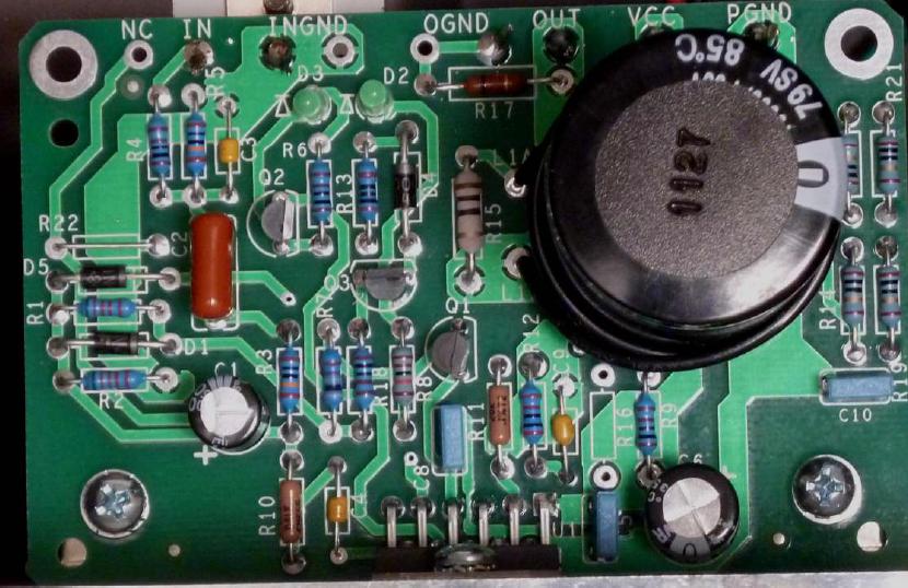
1) The picture I shown is just an EXAMPLE, not intended to use in any kind of productive design with LM3886.
2) This approach with additional metal parts are more appropriate for cases where we have 10s of power semiconductor mounted on heat sink and need to take cake on every dissipated Watts and applications where we need forced cooling with fans or water, usually in application >1kW.
3) It is a very bad idea to force so large dissipation on LM3886 for numerous reasons.
4) I don't have any measuring data for shown EXAMPLE due 1) 2) and 3)
5) I didn't claim anything regarding this example, just told "it helps" and instead I describe a VALID method to measure thermal conductivity so everyone can check that particular case or any other case.
6) I don't sell anything and everything I done so far is in public domain including project files (especially PCB) so everybody can try, modify or whatever they want to do with it.
7) I'm here to exchange ideas and experience which we collect on our local non-commercial forum where we have very respectable engineers which are behind shown cooling method.
8) Do not thread other people's ideas as "kids with toys" as they can be sometimes very useful. Many of those ideas can't be found in official books.
Is it OK now?
Last edited:
There is no data on power dissipation in the datasheet for +-12V, but we can do an approximation from figure 35. (Attached).
You can find the math in the data sheet or in a textbook such as Sedra/Smith, "Microelectronic Circuits". I've also included it on my website: Taming the LM3886 - Thermal Design. You'll probably also find the Excel worksheet at the bottom of the Taming the LM3886 - Power Supply Design page useful, as it does the math for you... 🙂
At ±12 V, 8 Ω load, the LM3886 will dissipate 4.8 W worst case (sine wave, Pout = Pout_max/2).
At ±12 V, 4 Ω load, the LM3886 will dissipate 8.4 W worst case (sine wave, Pout = Pout_max/2).
Above assumes an output drop-out voltage, Vod = 2.5 V, which is probably a bit pessimistic under these conditions.
~Tom
3) It is a very bad idea to force so large dissipation on LM3886 for numerous reasons.
Depends on what you consider "large dissipation". I would reword your statement as: It's a very bad idea to operate the IC beyond the absolute maximum junction temperature specified in the data sheet.
With sufficient heat sinking, I have no problem at all dissipating over 40 W in an LM3886 regardless of package. At ±28 V rails, 4 Ω*load, the LM3886 dissipates 42.5 W under worst case conditions (sine wave, output power = half the maximum output power).
Recall, the dissipated power is mostly Dissipated = (Vsupply - Vout) * Iout. With sine wave excitation, it's relatively straight forward to calculate the maximum dissipated power. It does require you to take the derivative of a sine wave, so some fancy arithmetic is required. You can find the full derivation in Sedra/Smith and the end result on my website. The end result is in the LM3886 data sheet, though I seem to recall there being a typo in the equation. The dissipation graphs in the data sheet are correct, the equation is not.
~Tom
Last edited:
Yes Tom, you correctly reword my statement, "It's a very bad idea to operate the IC beyond the absolute maximum junction temperature specified in the data sheet."
Even LM3886 have very good internal thermal protection they will not operate forever.
High temperature can melt down bounding wires which connect silicon die to the legs of the packaging.
As I remember, those bounding wires are made of silver and usually power pins have several (3-5) tiny wires so every time we "shock" IC we risk a lose of one or more wires.
IC will continue to work until we melt all it's bounding wires. It is interesting that silicon die can be still functional but that does not helps us, IC is generally destroyed.
This approach is done with intention to prevent more dangerous situations or fire, in other words they act as a fuse.
Of course, it is also in relation with over current situations.
Last edited:
Akitika GT-101
Perhaps you consider interesting:
Other amplifier with LM3886, by Dan Joffe
Akitika Store
And...
Perhaps you consider interesting:
...With sufficient heat sinking, I have no problem at all dissipating over 40 W in an LM3886 regardless of package. At ±28 V rails, 4 Ω*load, the LM3886 dissipates 42.5 W under worst case conditions (sine wave, output power = half the maximum output power).
~Tom
Other amplifier with LM3886, by Dan Joffe
Akitika Store
The recommended power supply voltage is a single 72 Volt DC supply. With a regulated 72 volt supply, the AMP01 delivers more than 50 Watts into an 8 Ohm load and nearly double that amount into 4 Ohms...
And...
Deep Finned Heatsink (HS101) - $20.00
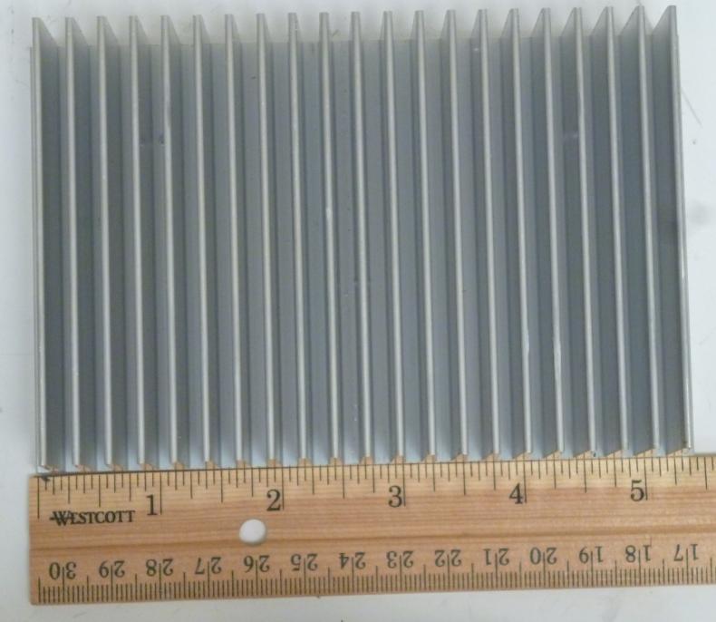
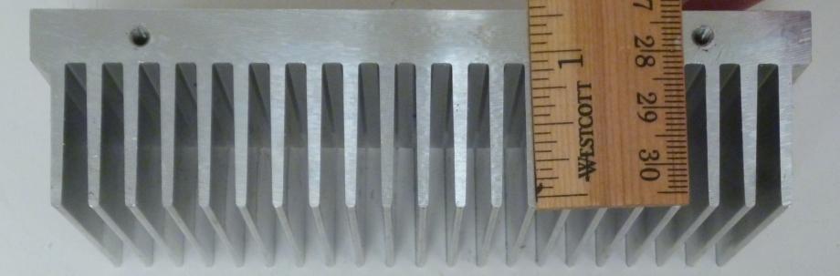
This large heatsink comes pre-drilled with 5-32 holes to accept either the AMP101 or a PSR101 module. It also has 6-32 mounting holes in the bottom that accept 6-32x3/8" screws to allow easy mounting on a chassis. The heatsink dimensions are 5.375"x 3.5" x 1.38". The distance between the bottom flange mounting holes is 3.875". This heatsinks is used in the GT-101.
@maty tinman
Every peace of heat sink is characterized with units of degrees Celsius per watt °C/W or K/W (it is the same from our point of view) for thermal resistance.
Usually larger and heavier heat sink have smaller thermal resistance, but that is not always a case (depends on many factors) so it is more relevant to taken an attention on manufacture's specification.
Thermal resistance means exactly that, how much our heat sink "resist" to transfer heat from mounted device to the ambient.
It is simple, if we have heat sink which is specified for example 1°C/W it means that for every 1W of dissipated power, temperature of heat sink will rise 1°C. We always need to calculate all this relatively because we have variable factor "ambient temperature".
In most home applications we chose for example worst case around 50°C for ambient temperature. If we have fan which "pump" air into case we can lower down internal ambient temperature and in general improve overall efficiency of our cooling system.
Next, any semiconductors device have an specification of it's thermal resistance of it's package and as described above all same rules apply for that.
Same thing is with insulators and thermal grace.
In practice it is not so easy to accurately calculate all this but we can have some good approximation, simple add all thermal resistance of each involved parts.
If you don't know exact thermal resistance of some salvaged heat sink, pick one which is larger, heavier, have more surface area, one which have better polished surface and pick BLACK colored 😉
This with color is interesting, you can paint it black if you want to lower down it's thermal resistance, but do not put excessive layer of color, just thin layer to become black colored (it is related to IR emission).
BTW: there are also an options to use not so common heat pipes or Peltier elements …
Last edited:
And would not it be more comfortable asking Dan Joffe the value of the thermal resistance of the heat sink?
Akitika does not use fan or...
And
By the way,
Would be very interesting a design of a PCB with negligible noise (mod-96 and parallel-86) and a regulated supply of 72V (Akitika) too, which would be the highest SNR!!!
Akitika does not use fan or...
And
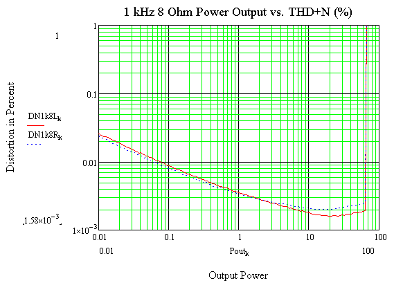
The next measurements show 1 kHz THD+N measurements as a function of output power across an 8 Ohm load. Note the clipping occurs around 63 watts. Both left and right channel measurements are shown. One channel was driven at a time for these measurements. The nice in THD+N at low output power levels is the usual rise that happens at low levels as a fixed amount of noise becomes a greater percentage of the THD+N as power drops.
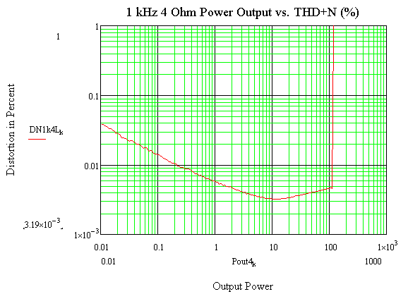
The next set of measurements is for 1 kHz 4 Ohm power versus THD+N. The GT-101, at 1 kHz, with a single channel driven, will put out more than 100 Watts in that channel, into a 4 Ohm load.
By the way,
Would be very interesting a design of a PCB with negligible noise (mod-96 and parallel-86) and a regulated supply of 72V (Akitika) too, which would be the highest SNR!!!
Last edited:
- Status
- Not open for further replies.
- Home
- Amplifiers
- Chip Amps
- LM3886 Thermal Experiment (with data)