Post99
The OUTPUT of the mixer is V1 * Rf/R1 + V2 * Rf/R2 + V3 * Rf/R3
If the three input channels are each 2Vac then the peak voltage on each input is 2.83Vpk.
If R1=R2=R3=Rf then the output is 8.5Vpk
The opamp must run from rails exceeding +-9Vdc and preferably >+-12Vdc.
The OUTPUT of the mixer is V1 * Rf/R1 + V2 * Rf/R2 + V3 * Rf/R3
If the three input channels are each 2Vac then the peak voltage on each input is 2.83Vpk.
If R1=R2=R3=Rf then the output is 8.5Vpk
The opamp must run from rails exceeding +-9Vdc and preferably >+-12Vdc.
I'm using an lm358 which uses single supply. So I dropped the voltage using the lm317 to around 13 volts, and the distortion sounds much better than yesterday but still far from usable. Doesn't really sound low pass either. The output is actually quite a bit lower than original input.
I'm using 220 ohm R's at the moment with low value caps at 0.47uf.
I'm using the inverting or - for the audio inputs. Shouldn't I use non-inverting?
I'm using 220 ohm R's at the moment with low value caps at 0.47uf.
I'm using the inverting or - for the audio inputs. Shouldn't I use non-inverting?
Last edited:
I quit, just going with 2 channels....I was altering my audio input and the negative touched the positive rail and jacked my phone up...
besides that, regardless of what values I put in it still sounds like crap, to much gain or not enough gain or to high pitched or whatever..
besides that, regardless of what values I put in it still sounds like crap, to much gain or not enough gain or to high pitched or whatever..
ok, I got the mixer working, sorta. The + connected to ground created static. So I put a cap from it to ground and that seemed to work. It sounds good but it's not low pass...
A mixer only ADDS signal together.
You still need a filter to create a Bass Only signal.
That was the beauty of the MFB filter: it is both a mixer for ADDING signal AND a Filter.
You still need a filter to create a Bass Only signal.
That was the beauty of the MFB filter: it is both a mixer for ADDING signal AND a Filter.
What's a MFB filter? I figure I'll use my quad op to create two single low pass filters for each channel and then feed that into the mixer circuit.
chasebank,
I highly recommend you read "Op Amp Applications" by Walt Jung, (Here) Technical Documentation | Resources & Tools | Analog Devices.
If you don't have a good basic grasp of Op Amps and how they work, there's little hope you'll have any real success.
Edit: For some reason the link doesn't go directly there, so click the link, check the "books and seminars" box, then go to page 4 to find "Op Amp Applications."
Mike
Last edited:
MFB stands for Multiple Feedback Bandpass filter" it is a type of filter configuration.
Much more info can be found here,
https://www.google.com/search?q=MFB...ome..69i57&sourceid=chrome&es_sm=122&ie=UTF-8
Also if you are using a Single Ended supply configuration on the Mixer/Filter opamp stage, you Must also, bias the opamp's with a virtual ground system set at half of the supply voltage.
https://www.google.com/search?num=1....12.0....0...1c.1.58.hp..0.16.774.mIRkIBrRPDs
This is explained in many threads here, and one that just recently was discussed on a similar design as this.
Here it is, it is a long thread but as you read the virtual ground system and the combining of single supplied circuits an Bipolar supply circuits is discussed as well,
http://www.diyaudio.com/forums/anal...ng-noob-preamp-single-supply.html#post3770760
Here are a few more,
http://www.diyaudio.com/forums/software-tools/185906-op-amp-virtual-ground-spice.html#post2518360
http://www.diyaudio.com/forums/cons...ue-combining-virtual-grounds.html#post4084070
http://www.diyaudio.com/forums/powe...virtual-ground-single-supply.html#post1197672
I use this type of setup when ever I am just using a few opamp's and have to use a single ended supply,
http://www.diyaudio.com/forums/powe...round-power-amp-applications.html#post2323212
As was pointed out you may have had to much gain for your mixer stage but reducing the power supply voltage should have not had made any difference in the amount of distortion you were getting, in fact it should have made it worse.
Typically reducing the supply would make it worse rather than making it better.
I am glad you got it working though.
The filters go after the mixer stage, and here again, you can also use your LM324's and then swap it out later for a higher quality Quad type such as the Tl074/84 or even better an LME49740.
Jer 🙂
Last edited:
I appreciate the help but this is all new to me and I'm trying to grasp it.
I'm confused about the virtual ground. So, I basically need to use one op to create a virtual ground, then use that as what my main ground? And use my actual ground as the -V?
Ok plugged in the lm324 and just created a virtual ground. Now I have to re-adjust my +v in as it's now -+ 4 volts ..
I'm confused about the virtual ground. So, I basically need to use one op to create a virtual ground, then use that as what my main ground? And use my actual ground as the -V?
Ok plugged in the lm324 and just created a virtual ground. Now I have to re-adjust my +v in as it's now -+ 4 volts ..
Last edited:
If you are just using a few opamp's in your circuit then you can use a simple resistor divider to get V/2 for the virtual ground.
But if you are using a whole lot of opamp stages then you need to have a low impedance virtual ground system.
This is best accomplished using a unity gain buffer opamp to supply the virtual ground line.
Or, you can reduce value of the resistors of the V/2 divider to allow more current flow. But, this unnecessarily eats power and raises the wattage rating requirement of the resistors.
Since you already have a Bipolar Supply configuration just adding the proper regulators will work the best and solve all of the issues of even having to have a virtual ground system at all, and all of the grounds will be common to the ground system as a whole.
There are certain rules you must follow when mixing the topology of both systems together and they are explained in some of those threads.
If you don't have the regulators you can also use a resistor voltage divider to drop the voltage on each half (+ and -) of your power supply to feed the opamp's +/- Vpins as well.
Opamps require only a small amount of current, so the resistors not need to be any low value and/or high wattage rating.
For instance, If your supply is at 45V as discussed earlier in this thread then you could use a 4.7k and a 1k resistors and this would drop the voltage to approximately 9.57V and they would only have to be 1/2watt types.
The actual power dissipation of the 4.7k resistor will be about .267 watts (267 milliwatt's) or so, and if you use 1/4 watt types they would be marginal and may eventually burn up and fail if used.
You would do this for both V+ and V- with the 1k connected to the ground bus.
These values will allow for about 7.538ma of current to feed the opamp with and this should be enough for your application.
You can also use a 3.3K instead a 4.7k and this will allow up to 9.5ma to supply the opamp and it will also raise the voltage to a nicer 13.63V range as well, But you must still use at least 1/2 watt types as the power dissipation will now be about .2982 (298.2 milliwatt's) for the 3.3k resistor.
You could also maybe use a 2.7k instead this would bring you to +/- 16.66v and a little more current for the opamp at 10.49ma. providing that your opamp can handle the voltage.
This is not a problem for the TL07x's but it may be just over the limit for a LM324 I will check the data sheet.
Yes, it is just over the limit for the LM324 as it is rated for 32V max, you can do the diode trick if you wish as well here, But there is no reason to need that much supply voltage for your application so stick with the 3.3k and 1k resistors with this method.
http://www.ti.com/lit/ds/symlink/lm124-n.pdf
I hope this helps.
jer 🙂
P.S. If I get some time a little later I will draw up a few examples in Circuitmaker 2000 to show you if you don't understand.
I got the mixer working, with the virtual ground. Been trying to figure the low pass configuration with no success. And now the mixer has static ...
I thought this would have been a simple addition to my project but it seems I underestimated op-amps. I'm running short on time and patience and I'm going to throw in the towel and just stick with the L and R channel of my amp sigh.
I'm still working on the VU meter for each channel as well. If this wasn't my final Capstone project then I would take my sweet time.
The reason the Opamp must be biased at V/2 is that this is the middle of its operating range.
This is the center point in order for it to swing the positive and negative halves of a ac signal without it distorting as the opamp can only swing with in its power supply voltage limits, 0v to V+ for a single ended supply or V- to V+ for a Bipolar supply configuration.
If the virtual ground is referenced to 0v then the ac signal can only swing from 0v to V+ and only the positive half of the waveform will be amplified and the negative half will be clipped and stay at a potential of 0v.
Just as a diode in a Half Wave rectifier configuration will do in a power supply circuit.
jer 🙂
I understand,
Like I said there are a few rules to go by when mixing the two types of configuratios of single ended supply and Bipolar supply opamp configurations.
The noise you are hearing my be from the use of low quality opamp's.
The LM324's are a bit noisy as well as they are basically Quad LM741's.
I used to use them in my Fuzz box's when I first started out and they where very noisy, especially in a circuit with a lot of gain, that was when I switched to using the TL07x's back in the day.
What a difference it made!!
My circuit suddenly became dead quiet using those instead.
I will draw up the simple solution using resistors for you as there is no reason to give up.
It is very simple, only you don't understand the simple rules just yet, but you will in time.
jer 🙂
I screwed up on my Voltage Divider calculation's and I do apologize for that.
I was doing it quickly in my head and I used the wrong formula.
Do use a 2.7K and a 1K for your divider.
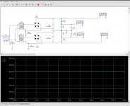
Here is the simulation I created to show the basic setup in circuit maker.
Ignore the values feeding the transformer as i didn't have the time to tweek those exactly as it was driven from the wall socket.
The output voltages are set exactly as you had described at 45v for the chipamp's.
I did not include the diodes or whatever you are using to drop that voltage for them.
The voltage out of the dividers are at +/- 12.15V for the opamp's and is sufficient to run them.
Do to my previous error I also check the simulation with a Voltage diivider Calculator just to be sure that it is correct , and it is.
Voltage Divider
The voltages are displayed in the meters, and, The Power Dissipation for the resistors is shown in the graph to be 400mw for the 2.7k resistor and 150mw for the 1k resistor.
The 100meg resistors are only there to make the simulation work in Circuitmaker 2000 and all of the ground points are referenced as a common ground.
This will end your virtual ground issue as this is the proper way to set up your power supply for your application without having to using regulators.
It also provides plenty of headroom for any line voltage fluctuations as well.
Cheers!!!
jer 🙂
P.S. What type of VU circuit were you planning?
A meter movement or an LED Bar Graph display type?
I was doing it quickly in my head and I used the wrong formula.
Do use a 2.7K and a 1K for your divider.
Here is the simulation I created to show the basic setup in circuit maker.
Ignore the values feeding the transformer as i didn't have the time to tweek those exactly as it was driven from the wall socket.
The output voltages are set exactly as you had described at 45v for the chipamp's.
I did not include the diodes or whatever you are using to drop that voltage for them.
The voltage out of the dividers are at +/- 12.15V for the opamp's and is sufficient to run them.
Do to my previous error I also check the simulation with a Voltage diivider Calculator just to be sure that it is correct , and it is.
Voltage Divider
The voltages are displayed in the meters, and, The Power Dissipation for the resistors is shown in the graph to be 400mw for the 2.7k resistor and 150mw for the 1k resistor.
The 100meg resistors are only there to make the simulation work in Circuitmaker 2000 and all of the ground points are referenced as a common ground.
This will end your virtual ground issue as this is the proper way to set up your power supply for your application without having to using regulators.
It also provides plenty of headroom for any line voltage fluctuations as well.
Cheers!!!
jer 🙂
P.S. What type of VU circuit were you planning?
A meter movement or an LED Bar Graph display type?
Attachments
Last edited:
Here is a very excellent video on opamp's that just got posted in this thread,
http://www.diyaudio.com/forums/chip-amps/264028-op-amp-example.html#post4108392
jer 🙂
http://www.diyaudio.com/forums/chip-amps/264028-op-amp-example.html#post4108392
jer 🙂
Part of my noise is my connection wire.
Since I ruined my phone, I'm now using my laptop and the wire isn't connecting properly and only feeding one channel and I wiggled it and noticed some obvious static. So I'm having other difficulties on top of difficulties..
Since I ruined my phone, I'm now using my laptop and the wire isn't connecting properly and only feeding one channel and I wiggled it and noticed some obvious static. So I'm having other difficulties on top of difficulties..
- Status
- Not open for further replies.
- Home
- Amplifiers
- Chip Amps
- Lm3886 problem