peufeu linked a 1k+10k array to (I presume) get the 20dB gain needed for 3886 stability. So the assumption Ad = 1 in thy maths is missing a zero. 😛 If you take a moment to look at the datasheet for the part you'll see it's four independent resistors, meaning the ratio spec is effectively "absolute" as it covers six possible resistor pairings. Thy maths therefore also haveth a denominator four times too large./me thinketh thy math is broken...
Beat might be optimistic; both resistor networks are likely made the same way. Matched TFR sets are typically offered in 1, 2, and 5 ppm grades (0.2 ppm if Vishay z-foil is included) with the tighter ones costing substantially more than THAT's parts. If one uses similarly priced amplifiers from Analog as proxies for THAT parts (because Analog does spec tempcos) most of the datasheets indicate 5 or 6 ppm tracking TCR typ.I would expect the THAT chips to meet or (more likely) beat the discrete resistor module on TCR.
Well, the difference between single ended and difference amplifier topologies is two resistors along with maybe a cap and perhaps a third resistor to even up a source with unbalanced impedances. With 0.5% being a default resistor tolerance the ROI on adding two of them to the BOM to go from 0dB to 40dB CMRR is pretty high. Instruments are about the only thing in pro audio which doesn't use balanced interconnects. The de facto standard for amps and pedals and such which are therefore single ended is TL072 difference amplifiers with remote ground sense, 10k resistors, and 220pF lowpass caps. The majority of home audio/hi-fi is rather lacking in comparison.I mentioned the differential circuit as "food for thought", not "you must do it like this or you're an idiot" 😉
The LM3886 by itself performs quite well. On a good board you can manage the signal integrity to wring out the performance published in the data sheet (or a bit better as is the case in my circuit). My preference is therefore to stick a differential front-end on the LM3886. A THAT1200 is a solid performer, so that's what I'd go with.
Turning the LM3886 into a differential amp as you've done would be another option. Note, though, that the input impedances on the IN+ and IN- inputs are different and rather low. You can fix this by adding an instrumentation amp front-end (two op-amps, three resistors) to your diff amp. An LME49720 would be an excellent candidate for the front-end.
~Tom
peufeu linked a 1k+10k array to (I presume) get the 20dB gain needed for 3886 stability. So the assumption Ad = 1 in thy maths is missing a zero. 😛
Sigh... Fine! 🙄 🙂 Yeah, I missed that it was a 10k,1k array. I was thinking 1x input buffer...
I stand corrected.
Well, the difference between single ended and difference amplifier topologies is two resistors along with maybe a cap and perhaps a third resistor to even up a source with unbalanced impedances. With 0.5% being a default resistor tolerance the ROI on adding two of them to the BOM to go from 0dB to 40dB CMRR is pretty high. Instruments are about the only thing in pro audio which doesn't use balanced interconnects. The de facto standard for amps and pedals and such which are therefore single ended is TL072 difference amplifiers with remote ground sense, 10k resistors, and 220pF lowpass caps. The majority of home audio/hi-fi is rather lacking in comparison.
I agree. In consumer audio every resistor counts against your margins. It's amazing single ended audio works as well as it does. It is no surprise, however, that the pro guys are using differential signaling. They're the ones running gobs of cable and connecting components across different power domains.
~Tom
Very true. However, pro audio's not a high margin business either and a fair number of the difference amps deployed are used over short distances within the same mains circuit. Patch bays, either rackmount or guitar pedalboard, are common cases. As another example, Peavey uses remote ground sense and diff amps for six inch board to board runs inside some (if not all) of their low cost 3886 based amplifiers. So I think it's more about the level of sound quality demanded by customers in the different market segments.
DIYers are (hopefully) closer to the pro audio market profile than consumer audio. Much of what this thread's about is power amps pull enough current it's useful to treat them as a distinct power domain to more reliably meet those expectations. Which is refreshing as all too often that gets lost in all the grief over the pin 1 problem. Good stuff; keep it coming.
DIYers are (hopefully) closer to the pro audio market profile than consumer audio. Much of what this thread's about is power amps pull enough current it's useful to treat them as a distinct power domain to more reliably meet those expectations. Which is refreshing as all too often that gets lost in all the grief over the pin 1 problem. Good stuff; keep it coming.
Will do. I'm looking forward to seeing all of this coming together. Patience young grasshopper. Patience...
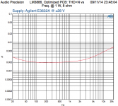
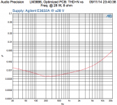
So... A while back, I promised to show THD data for an LM3886 using a real supply (transformer + rectifier + electrolytic capacitors) versus the rather nice Agilent E3632A I normally use. I may work a bit slow, after all, I do want to enjoy the summer outside rather than in the lab, but I do follow through on my commitments. The data is attached. The THD+N was measured using an Audio Precision SYS-2712.
Lab Supply Method & Results: The lab supply was an Agilent E3632A adjusted to ±28 V with the current limit set to 4.125 A (as high as it can go on that supply). The resulting THD+N curves are slightly better than the published data sheet performance of the LM3886, likely because I'm using a gain of 11 (feedback network: 10k, 1k, 1 %) rather than the gain of 20 that I'm guessing NSC used when making the plots. It is also possible that my layout is better than that of the LM3886 evaluation board. I don't have the original eval board, so I can't verify this.
The results are in line with what I published earlier and show no surprises. Max. power out is about 28-30 W. That's when the LM3886 starts clipping.
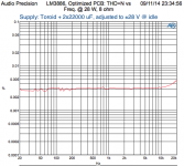
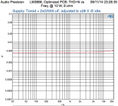
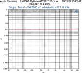
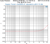
Real Supply Method & Results: The supply was comprised of a variac providing an adjustable mains voltage to a 530 VA toroid transformer. The transformer output voltage was rectified using a 25 A bridge rectifier and smoothed using two 22000 uF capacitors (one cap per voltage rail). The LM3886 part of the circuit was completely unchanged.
The resulting THD+N performance is quite a bit worse than with the lab supply. This actually was a surprise to me as I would have thought the supply rejection of the LM3886 would have taken care of any supply ripple and signal-dependent "garbage". That's clearly not the case.
The max output power is about 25-26 W. This is no surprise. With the unregulated supply, the supply voltage droops as the load current (output power) increases. So when the amp is providing 25 W to the load, it's running on about ±26 V versus ±28 V at idle. No surprises there.
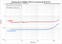
Now, the good news is that I do have an amplifier design that will both beat the LM3886 stand-alone THD+N performance by a factor of 10x (using a real supply) and offer much superior supply rejection. My new amp design (I call it Modulus-86) shows the exact same excellent THD+N performance whether used with a lab supply or a real supply. It turns out supply rejection is a good thing... 🙂
~Tom
Lab Supply Method & Results: The lab supply was an Agilent E3632A adjusted to ±28 V with the current limit set to 4.125 A (as high as it can go on that supply). The resulting THD+N curves are slightly better than the published data sheet performance of the LM3886, likely because I'm using a gain of 11 (feedback network: 10k, 1k, 1 %) rather than the gain of 20 that I'm guessing NSC used when making the plots. It is also possible that my layout is better than that of the LM3886 evaluation board. I don't have the original eval board, so I can't verify this.
The results are in line with what I published earlier and show no surprises. Max. power out is about 28-30 W. That's when the LM3886 starts clipping.
Real Supply Method & Results: The supply was comprised of a variac providing an adjustable mains voltage to a 530 VA toroid transformer. The transformer output voltage was rectified using a 25 A bridge rectifier and smoothed using two 22000 uF capacitors (one cap per voltage rail). The LM3886 part of the circuit was completely unchanged.
The resulting THD+N performance is quite a bit worse than with the lab supply. This actually was a surprise to me as I would have thought the supply rejection of the LM3886 would have taken care of any supply ripple and signal-dependent "garbage". That's clearly not the case.
The max output power is about 25-26 W. This is no surprise. With the unregulated supply, the supply voltage droops as the load current (output power) increases. So when the amp is providing 25 W to the load, it's running on about ±26 V versus ±28 V at idle. No surprises there.
Now, the good news is that I do have an amplifier design that will both beat the LM3886 stand-alone THD+N performance by a factor of 10x (using a real supply) and offer much superior supply rejection. My new amp design (I call it Modulus-86) shows the exact same excellent THD+N performance whether used with a lab supply or a real supply. It turns out supply rejection is a good thing... 🙂
~Tom
Attachments
-
 LM3886_LabSupply_1W.png51 KB · Views: 933
 -
 LM3886_RealSupply_28W.png49 KB · Views: 335
 -
 LM3886_RealSupply_10W.png50.2 KB · Views: 867
 -
 LM3886_RealSupply_1W.png52.6 KB · Views: 866
 -
 LM3886_LabSupply_28W.png53.8 KB · Views: 898
 -
 LM3886_LabSupply_10W.png51.2 KB · Views: 931
 -
 LM3886_Schematic.png62.5 KB · Views: 1,315
Last edited:
Well... I have a lot of information to collect and put into a presentable form. I expect to have a good portion of that done this weekend and will publish the design (and open up for board sales) at that time. I'll make a post here and start a separate thread for the Modulus-86 once I'm ready.
Meanwhile, enjoy the attached plots of the THD+N performance (measured using the same setup as I used for the LM3886 in Post #247).
~Tom
Meanwhile, enjoy the attached plots of the THD+N performance (measured using the same setup as I used for the LM3886 in Post #247).
~Tom
Attachments

Last edited:
Good stuff!
Looks like a composite amp, or somthing with error correction (a la Bonsai's AFEC, for example) ;-) At least I cannot think another way to get that much better performance.
Looks like a composite amp, or somthing with error correction (a la Bonsai's AFEC, for example) ;-) At least I cannot think another way to get that much better performance.
Yep. It's a composite. It's the best performing semiconductor amp I have ever designed, including various discrete designs. This both in terms of measured performance and perceived sound quality. I really like it.
I'll have to wait until next weekend before going fully public with this. The water line that goes to my house is leaking at a very rapid rate, so I'm currently digging holes in my front yard trying to find the leak. Until that's fixed, I won't have much time or energy for audio, sadly. Stay tuned...
~Tom
SPICE LM3886 model?
Dear Guru tomchr, please excuse me if you have already answered this question. But I'm busy downloading all your words of wisdom on this forum and your webpages and it will be some time before I get to study all of them.
I'm after an 'accurate' SPICE model for LM3886. It's for work on a Transconductance Amp ie HiZ output.
Which one do you like for stability etc?
My concern is the Zobel. IMHO, its impossible to guarantee stability into ALL POSSIBLE SPEAKER LOADS in a normal low Zo amplifier with acceptable THD.
But a Zobel kills the high Zo of a Transconductance Amp at HF. So I need to play with it in SPICE world to see what can be done .. or NOT done.
But a Zobel kills the high Zo of a Transconductance Amp at HF. So I need to play with it in SPICE world to see what can be done .. or NOT done.
I used the TINA-TI SPICE model published by TI. I used TINA-TI for the simulations. It works pretty well, but as you'd expect from an engineering tool, it comes with its own set of quirks.
You can see my comments about the model in the stability section of my Taming the LM3886 page.
~Tom
You can see my comments about the model in the stability section of my Taming the LM3886 page.
~Tom
stupid question(s)
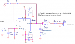
I've decided to copy your LM3886 schematic/design because you put "Engineering : : Done : : Right" in big letters on your website and you use a lot of sciencey looking graphs on it too.
Do you have a schematic or does anyone have one an idiot can "read"?
I get most of the schematics in the thread and on your website, but then there's always something weird in one lol You know what I mean 😀
Also what parts I should get is not totally clear lol
Man this guy kind of looks like me
I've decided to copy your LM3886 schematic/design because you put "Engineering : : Done : : Right" in big letters on your website and you use a lot of sciencey looking graphs on it too.
Do you have a schematic or does anyone have one an idiot can "read"?
I get most of the schematics in the thread and on your website, but then there's always something weird in one lol You know what I mean 😀
Also what parts I should get is not totally clear lol
Man this guy
kind of looks like meDepends on what you'd like to build. It sounds like you're looking for a basic LM3886 build. I suggest starting with the Typical Application Schematic in the LM3886 data sheet (Figure 1). I do recommend adding a Zobel and a Thiele network, however. So 2.7 Ω in series with 100 nF from the output to ground and 10 Ω in parallel with 1 µH in series with the speaker output. Those components are needed for stability.
If you're looking for a solution that's a bit closer to plug-n-play and want state-of-the-art performance, I suggest looking at my Modulus-86.
~Tom
If you're looking for a solution that's a bit closer to plug-n-play and want state-of-the-art performance, I suggest looking at my Modulus-86.
~Tom
Depends on what you'd like to build. It sounds like you're looking for a basic LM3886 build. I suggest starting with the Typical Application Schematic in the LM3886 data sheet (Figure 1). I do recommend adding a Zobel and a Thiele network, however. So 2.7 Ω in series with 100 nF from the output to ground and 10 Ω in parallel with 1 µH in series with the speaker output. Those components are needed for stability.
If you're looking for a solution that's a bit closer to plug-n-play and want state-of-the-art performance, I suggest looking at my Modulus-86.
~Tom
I saw your Modulus-86 webpage last night, but I already have half the parts for a LM3886 amp.
I was trying to isolate one schematic to follow on your LM3886 webpage, but for some reason I couldn't do it. Maybe I was tired and couldn't figure it out. I'll try looking at it again. I want to build mostly a P2P amp (partly compact PCB type also). I'm pretty decent at layouts and soldering, so this thread was particularly interesting. Also I have to fit a 4-channel lm3886 amp in a very small (thin) box.
I have a little bit same situation as Jimmy. I have been thinking the most convenient yet simple way of building my first LM3886 based amp.
In your post #247 there is a schematic that I'm very keen on building and testing. Before starting to build I would like to ask few questions. What is the suitable wattage for resistors that don't have it marked (R1, R2, R9, R10), current rating for L1 and voltage rating for C8?
I will be probably using P2P method. I know the result won't be top notch hifi like your Modulus, but I will try to learn the basics before trying something that ambitious.
Thanks
- Home
- Amplifiers
- Chip Amps
- LM3886 PCB vs Point-to-Point (with data)