I have a little bit same situation as Jimmy. I have been thinking the most convenient yet simple way of building my first LM3886 based amp.
In your post #247 there is a schematic that I'm very keen on building and testing. Before starting to build I would like to ask few questions. What is the suitable wattage for resistors that don't have it marked (R1, R2, R9, R10), current rating for L1 and voltage rating for C8?
I will be probably using P2P method. I know the result won't be top notch hifi like your Modulus, but I will try to learn the basics before trying something that ambitious.
Thanks
WARNING the following are all guesses:
I think the resistors are like .5W, but don't take my word for it. They're like typical .25-.5W resistors. You could get 2W when in doubt I suppose.
C8 is a tiny cap. I think the voltage rating on it is rather insignificant also.
Same with the L1 doesn't need a rating because the wire will be relatively thick I would imagine.
I'm more confused about HV+ and HV-
I don't know what those are at all.
I think the dashed grounds go to some sort of common ground (star ground perhaps?).
I think the solid ground, or I've seen it draw as solid before, goes to the negative power supply . . . it's not called output, I guess PS ground then.
This thread kind of help me with the P2P drawings. I think I can piece it together maybe.
I found one P2P LM3886 webpage with pictures that I could copy, but I like all the graphs and what-not lol
It's a good idea to find the seemingly smartest guy and just copy him. Or at least the most sciencey guy.
The Modulus 86 is a commercial offering in Vendors section.
So far Tomchr has refused to give details.
He will sell you a pair of PCBs for $120.
So far Tomchr has refused to give details.
He will sell you a pair of PCBs for $120.
In your post #247 there is a schematic that I'm very keen on building and testing. Before starting to build I would like to ask few questions. What is the suitable wattage for resistors that don't have it marked (R1, R2, R9, R10), current rating for L1 and voltage rating for C8+
For everyone's benefit, here's the schematic we're talking about:
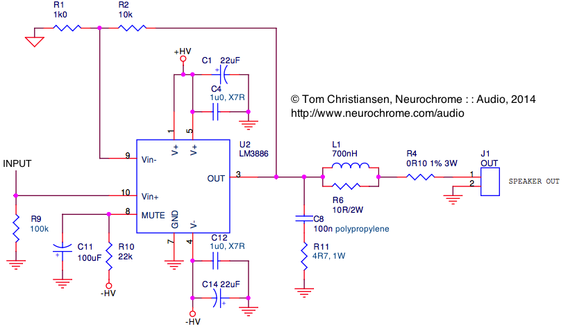
Opamp background: If the opamp has negative feedback and sufficient loop gain, it will drive the output voltage to the point where the input differential voltage is zero. I.e. Vin(+) = Vin(-). Thus, the voltage across R1 is the same as the input voltage, i.e. the voltage across R9. Assuming ±28 V rails and 1.6 V drop-out across the LM3886, the worst case output voltage is ±26.4 V (= 26.4/sqrt(2) = 18.7 V RMS). The gain is 1+R2/R1 = 11 V/V, so the input voltage is 18.7/11 = 1.7 V RMS.
Power dissipated in R1: 1.7^2/1E3 = 2.88 mW
Power dissipated in R9: 1.7^2/100E3 = 28.8 µW
R2 sees Vout-Vin, but with AC voltages, the phase difference needs to be taken into account, which complicates the math. However, Vout >> Vin --> Vout-Vin ~= Vout.
Power dissipated in R2: 18.7^2/10E3 = 35 mW
From the equivalent circuit schematic of the LM3886 (in the data sheet), the voltage at the mute pin can be deduced to be -3*Vbe, where Vbe is the base-emitter voltage of the three NPNs in the mute circuit. Vbe in most silicon processes is about 0.7 V, so the voltage across R10 is 28-3*0.7 = 25.9 V.
Power dissipated in R10: 25.9^2/22E3 = 30.5 mW
The power dissipated in the Zobel resistor, R11, is a bit trickier to calculate. On my Taming the LM3886 page, I describe how to do the math. Rather than typing it all again, I suggest you read through the section about the Zobel network.
The resistor in the Thiele network is generally a few watt. I used a 2 W type.
The inductor in the Thiele network is an air core inductor. This means the saturation current is limited by the ampacity of the wire rather than the core material. Build yourself an air core inductor with an inductance around 0.7~1 µH. You can figure out the dimensions using one of the many on-line inductance calculators.
~Tom
The Modulus 86 is a commercial offering in Vendors section.
So far Tomchr has refused to give details.
I strongly disagree with that statement. I have provided several references, a block diagram, as well as a list of the ICs used. That's more than enough for anyone skilled in the art to reproduce the circuit at their leisure. I have provided significantly more detail, data, and measurements than you'll get from most commercial vendors.
The Modulus-86 offers a very strong value proposition. I think it's pretty reasonable to charge for that rather than just giving it away for free. Others obviously disagree.
~Tom
For making good PROFITABLE business, one needs to carefully think what is the best price for the item to be sold.
I think the PCBs are a bit on the expensive side, if one takes into account that one can get really great quality double sided 1oz 10cm*10cm GOLD plated PCBs from China for 5$/pc nowadays.
I might find selling those pcbs for lets say a reasonable 200% margin still to be quite profitable and should still cover the massive work behind the concept in the long run. Hopefully soon because of the blooming business...
But thats only my opinion.
Excellent project and data however! Thankyou for that. Been following your findings with great interest!
Thoroughly impressive work.
In a certain sense, P2P is one kind of PCB. Different layout & routing causes parameter differences.
Tomchr, because you have decided not to publish the schematic of the Modulus 86, which I fully understand, I feel it would not be correct to even attempt to construct a schematic based on your work and then to post it here.
Most do not realise how little protection a design really has.
Most do not realise how little protection a design really has.
For everyone's benefit, here's the schematic we're talking about:
Turns out I'm stupider than I thought 😀
+HV is from the power supply positive and -HV is from the PS negative.
And input is input lol

And I think the solid (non-hashed) ground symbol is to the input ground, correct?
And all the hashed grounds go to the star/common ground.
Do I have this right?
What no, the 100k resistor (R9) goes to the input ground, right?
I don't know where the solid ground goes.
Last edited:
For making good PROFITABLE business, one needs to carefully think what is the best price for the item to be sold.
I think the PCBs are a bit on the expensive side, if one takes into account that one can get really great quality double sided 1oz 10cm*10cm GOLD plated PCBs from China for 5$/pc nowadays.
A Ferrari sells for $120k but contains $5k in raw materials. That's just not fair! A Ferrari should only cost $12k. That's basically your argument, right. I'm sure you can find the fallacy here... 🙂
I might find selling those pcbs for lets say a reasonable 200% margin still to be quite profitable and should still cover the massive work behind the concept in the long run. Hopefully soon because of the blooming business...
Margin is profit/sales, hence, the margin cannot exceed 100 %. A 100 % margin would be selling a free product at a profit.
I understand your point. To make a profit, one must make money on each sale, i.e. have a profit margin. If the supply/demand curve is completely elastic, the demand would drop if the price is increased. However, DIY Audio, I think, is a rather inelastic market. First off, the number of buyers is very limited. The subset of available buyers who would buy my product is very limited. Basically, I cater to the part of the DIY crowd who care about performance and are willing to pay a little extra to get it. In an inelastic supply/demand situation, lowing the price will not increase sales. It will only decrease profits. I operate in a low volume, high margin business and have priced my products accordingly.
One thing I have learnt from this Neurochrome business is that it's hard to make money. I'm glad I'm not doing it for a living... 🙂
No offense taken by the way. You're entitled to your opinion.
Excellent project and data however! Thankyou for that. Been following your findings with great interest!
Thoroughly impressive work.
You're very welcome. That's what you get when you buy my products. You get the confidence and peace of mind that once you've assembled your boards, they'll match the performance I'm measuring on mine. You buy the expertise and engineering that went into them. That considered, the boards should cost more... Better buy now before I raise the prices... 😉
Tomchr, because you have decided not to publish the schematic of the Modulus 86, which I fully understand, I feel it would not be correct to even attempt to construct a schematic based on your work and then to post it here.
I'll be happy to help anybody who starts a thread on composite amps with their designs. However, they'd have to do the work. If they'd rather pay me to do the work, I have two options: They can buy my boards or they can hire me as a consultant/tutor on their project.
The composite amplifier is not my IP. The Modulus-86 is my IP....
Most do not realise how little protection a design really has.
Tru dat.
~Tom
And I think the solid (non-hashed) ground symbol is to the input ground, correct?
Put R1 to the same ground as everybody else. You will get the best performance if R1 and R9 go to the ground connection by the speaker terminal. You'll have to wait until I get the bits about grounding typed up for my Taming the LM3886 Page to get the reasons why.
~Tom
A Ferrari sells for $120k but contains $5k in raw materials. That's just not fair! A Ferrari should only cost $12k. That's basically your argument, right. I'm sure you can find the fallacy here... 🙂
Or is it more like a Volvo with just an ordinary Ford engine?
😉
Jimmy,
post268 diagram is confusing because all but one ground uses the same symbol.
C4 connects to C12. = HF decoupling ground.
C1 connects to C14. = MF decoupling ground.
Connect these two decoupling grounds. = main decoupling ground.
You MUST obey the HF and MF decoupling rules on trace/lead lengths. This is more than VERY IMPORTANT.
R11 connects to main decoupling ground.
Connect PSU Zero Volts to main decoupling ground. This now becomes the Amplifier Power Ground.
Connect Speaker Return to Amplifier Ground. This now creates the Main Audio Ground.
The location of the Main Audio Ground can be chosen to be anywhere along the speaker cable return wire. It could be at the chassis mounted speaker return terminal or at the PCB Power ground or in between. I try to choose a location that minimses the length/distance to all other parts of the amplifier that need to reference this virtual point. These are the Chassis input terminals, the amp PCB inputs, the amp PCB outputs and the speaker terminals.
Connect Signal Ground to Main Audio Ground. This works for a mono block. Stereo and all other multi-channel amplifiers are different.
Connect R1 to R9 = Signal Ground
Connect input socket Signal Return to the Signal Ground.
Tomchr,
does any of the above disagree with your conclusions?
Multi-channel change/difference.
Disconnect the direct trace/wire link from Signal Ground to Power Ground.
Insert a low value resistor, usually 2r2 to 22r works well.
This references the signal input to the signal output. Virtually no signal current passes through this resistor and thus there is virtually no signal voltage across this resistor.
BUT !!!!!
interference currents and Fault Currents will flow through this resistor.
This develops a voltage drop for VHF interference and for 50/60Hz and it's harmonics.
Let's deal with the Fault Current first.
For operator safety, the Signal Ground to Power Ground connection must remain intact even during and after a catastrophic mains failure.
This can be helped by adding power diodes in inverse parallel combination to pass the hundred amps or so of peak fault current that may have to flow along this escape route.
Back to the hum.
The signal ground to power ground for a two, or more, channel amplifier , creates a loop when the two interconnects have a common signal ground at the remote end.
To reduce the hum voltage on the signal return leg of the two wire signal connection, the hum current must be reduced. The added resistor increases the resistance of the hum loop. But importantly by locating the resistor BETWEEN Signal Ground and Main Audio Ground does NOT add hum voltage into the signal's two wire connection. If the added resistor is 10r and the hum loop resistance from Source common ground into the amplifier and all the way back to the Source adds up to 1r, then the current is reduced to ~1/10th of it's previous value. The hum voltage (on the signal return wire) is attenuated by ~20dB.
If the interconnects and the source common ground resistance and the amplifier wires/traces added up to 0r1 of total resistance, then a 10r added resistor would attenuate the hum voltage by ~ 40dB. The resistance of the hum loop can be measured. For very low values you may find that the added resistor works, when at the low end of the suggested range.
Read Joffe. I have consigned his name to memory (RAM or ROM?), I found his paper quite a few years ago.
Last edited:
Thank you very much for all the info Tom and Andrew. I guess will be reading that grounding scheme a few times before heating up the soldering iron, but now it's time to do some part shopping. 😀
Yep. It's a composite. It's the best performing semiconductor amp I have ever designed, including various discrete designs. This both in terms of measured performance and perceived sound quality. I really like it...~Tom
Did you performed blind ABX testing?
As for 120$ for a pair of PCBs, even though the price is pretty steep (not all DIYers earn in $), I think its still cheaper & well documented than 47 Labs "Gaincard". If there is still market for "Gaincard" then hopefully there will be market for Modulous-86 also. I wish good luck & good business to you.
Last edited:
post268 diagram is confusing because all but one ground uses the same symbol.
My bad... 😱
Tomchr,
does any of the above disagree with your conclusions?
I don't see the need to separate into MF, HF decoupling grounds.
The name of the game is inductance. Minimize inductance. Every mm of wire has about 1 nH of inductance. Flat, wide wire has less inductance than round wire. This is why braid is used for grounding in HF circuits (older circuits, back when the impedance of a braid was low at the operating frequencies of the circuit).
For the decoupling to work well, it must be connected to the LM3886 using low-inductance connections. So minimize the lead length here. Get the decoupling caps as close to the LM3886 as possible. See my Taming the LM3886 Page for the optimum decoupling network. This takes care of C1, C4, C12, and C14. Put two 1000 uF, 50 V electrolytic caps where the power comes into the circuit and connect these to the decoupling networks with as short wires as you can. Now you have a sizable ground blob where the six caps meet. Let's call that the decoupling ground.
Connect the Zobel network with as short connections as possible to the decoupling ground. Connect the GND pin on the IC to this ground as well. Run a wire from the decoupling ground to the speaker output ground post. Take the feedback ground (R1) and input reference ground (R9) from the speaker ground post.
C11 grounds at the decoupling ground.
Again: Minimize inductance. Go back to around Page 4 of this thread to see the impact of inductance on the circuit performance.
Multi-channel change/difference.
Disconnect the direct trace/wire link from Signal Ground to Power Ground.
Insert a low value resistor, usually 2r2 to 22r works well.
This references the signal input to the signal output. Virtually no signal current passes through this resistor and thus there is virtually no signal voltage across this resistor.
BUT !!!!!
interference currents and Fault Currents will flow through this resistor.
This develops a voltage drop for VHF interference and for 50/60Hz and it's harmonics.
This I strongly disagree with. You actually describe the reason why in the paragraph above. You are absolutely right that an error signal (interference, for example) will cause an error voltage across the resistor. However, that error voltage will now be in series with your input signal as it lifts up the input reference ground. The result is that the EMI will see the full gain of the amplifier. That's exactly what you don't want.
You can easily convince yourself of this if you build an LM3886 in your favorite circuit simulator and use an AC source to inject an error current onto the reference net. You'll notice that the voltage on the output of the amp increases as that ground resistor is increased.
~Tom
Did you performed blind ABX testing?
No... I didn't have the budget to pay 250 people to audition my amp... 🙂
As for 120$ for a pair of PCBs, even though the price is pretty steep (not all DIYers earn in $), I think its still cheaper & well documented than 47 Labs "Gaincard". If there is still market for "Gaincard" then hopefully there will be market for Modulous-86 also. I wish good luck & good business to you.
My price is about 2/3 of what Twisted Pear charge for their composite amp. I think I'm in the right ballpark.
I appreciate your comments on the documentation and such. Thanks! My goal is to provide well-engineered, well-documented projects so the people who build them will have the highest chance of success with the their build.
~Tom
Dude, your tests alone are worth the price of admission. Cleared up so much mystery for me that I started looking for the donate button 😉
The only thing I could have wished for? More information about the higher order harmonic distortion. Incidentally, the resistor layout on your webpage looks alot like the way Rowland did it in his Concentra.
The only thing I could have wished for? More information about the higher order harmonic distortion. Incidentally, the resistor layout on your webpage looks alot like the way Rowland did it in his Concentra.
Tom, can you please put a date on the page if you make a significant change to that page.Put R1 to the same ground as everybody else. You will get the best performance if R1 and R9 go to the ground connection by the speaker terminal. You'll have to wait until I get the bits about grounding typed up for my Taming the LM3886 Page to get the reasons why.
I'm following this very closely and that would help us unwashed masses to know when somthing has changed
____________________
I think $120 for the PCBs is good value. Certainly better value than Golden Pinnae caps/wires/resistors which don't result in better performance and sound.
Earthing, Decoupling & Layout have FAR greater effect on performance & sound than Golden Pinnae parts .. unless you are deaf. (Most Golden Pinnae are deaf 😱 )
- Home
- Amplifiers
- Chip Amps
- LM3886 PCB vs Point-to-Point (with data)