if you could source for custom wound toroid then by all means proceed with your multiple voltage config. maybe afterwards after the amp is built you could try and run it with different voltage to hear if there's any audible difference between running the amp at different voltages.
I propose that you check the circuit in Spice to see the effect. C1 and Cf1 form a frequency-dependent voltage divider and changing either will affect the entire response. Their values need to fit to each other.
I made a model in LTspice and tried running it, however I am not able to run this. I am a complete newbie on this and need some help here.
I am attaching the schematics and model in ZIP file, if some one can run this model and check it will be of great help...
or guide me how to run this 🙂
View attachment Bridge Amplifier schematics.zip
The ZIP file includes
LM3886.sub - model
LM3886.sym - LTspice autogenerated symbol
LF411.mod - LF411 model
Bridge Amp schematic - circuit model in LTspice (Pic below)

if some one can run this model
LTSpice does not work with the .mod extension. Rename the LF411 file to .sub, then you should get results. I have the LF411.sub file in the corresponding LTSpice folder and after deleting the include command, your file worked.
The LM3886 model is not realistic. All transistors in it are ideal models, and the current source values are all guessed. Especially for the purpose of determining compensation this model is not useful, because it does not behave like the real LM at high frequencies.
Thanks Pacificblue for trying this.
Did you notice any issue with the circuit in Spice, or it seems fine?
I could not find any LM3886 model on National Website. Is there any reliable LM3886 model available to simulate this?
I am still not able to run the model. I have changed the include file to (.include LF411.sub).
I see something happening in status bar below (image below), but do not get the black screen with charts.

What is the simulation command you are using? I used .ac dec 20 20 100
Did you notice any issue with the circuit in Spice, or it seems fine?
I could not find any LM3886 model on National Website. Is there any reliable LM3886 model available to simulate this?
I am still not able to run the model. I have changed the include file to (.include LF411.sub).
I see something happening in status bar below (image below), but do not get the black screen with charts.
What is the simulation command you are using? I used .ac dec 20 20 100
Yes, the file works fine.
No, there are no reliable spice models around.
I used the same simulation command.
In your file Spice looks for LF411/NS, which is not the same as LF411. The op amp value must be changed to LF411.
I already had the LF411 model renamed to LF411.sub in my *\LTC\LTspiceIV\lib\sub\ directory, so I could delete the include command. In theory your method should work the same, provided you have the file in the same directory as the sim file. Either that or you have to state the complete directory path in the include command as well.
Bode Plot Approximation for LM3886
Hi,
Here is my try on making a proper AC model of the LM3886.
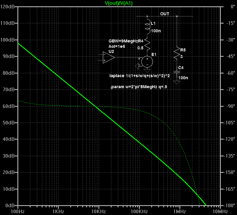
U2 is the standard single pole OpAmp (LT's opamp.sub) with parameters made visible and adjusted.
E1 introduces a set of higher poles. For convenience a squared 2nd order lowpass was choosen, with f0 and q selected to provide a close fit of the magnitude and especially the phase response compared to the published plot.
Zout -- required to see the effect of load capacitance -- is more or less guesswork based on the datasheet (R) and some minimum assumed open-loop output inductance. A zobel was simulated, too, because it tapers the open-loop transfer a bit as well, although usually higher up and not very significant for the phase margin at the intercept with the typical 26dB closed-loop gain.
Hi,
Here is my try on making a proper AC model of the LM3886.
U2 is the standard single pole OpAmp (LT's opamp.sub) with parameters made visible and adjusted.
E1 introduces a set of higher poles. For convenience a squared 2nd order lowpass was choosen, with f0 and q selected to provide a close fit of the magnitude and especially the phase response compared to the published plot.
Zout -- required to see the effect of load capacitance -- is more or less guesswork based on the datasheet (R) and some minimum assumed open-loop output inductance. A zobel was simulated, too, because it tapers the open-loop transfer a bit as well, although usually higher up and not very significant for the phase margin at the intercept with the typical 26dB closed-loop gain.
Attachments
Of course, I am assuming I will be able to get two custom made toroid with 3 pair of secondaries each to give output rails of 25V, 35V and 21V for Woofers, midrange and tweeters respectively.
One toroid for all right side speakers and one for all left side speakers.
The Toroid will be common and each channel will have it's own 2 secondaries, bridge rectifier pair, filter / reservoir Capacitor, etc.
The Custom transformer with 3 secondary was designed and ordered, I should be receiving it in 1-2 weeks.
Meanwhile I was working on the wiring plan. The sketch shows how I intend to wire the amplifier and the PSU. The wiring is planned in a way that they do not intersect each other.
This is the rear view of the speaker, the lower black box is the PSU and the Upper black box is going to be the amplifier with heat sink on top and back side. I am planning to mount the ASP (Active crossover) within the amp case itself.

Following DC wires will be connected from PSU to Amp(& ASP) – shown in orange colour
+/- 21 V for Tweeter Amplifier (3 Amps)
+/- 25 V for Woofer Amplifiers (5+5 Amps)
+/- 35 V for Midrange Amplifier (2.7 Amps)
+/- 15 V for ASP and Voltage follower in woofer Bridge circuit
+/- 20 V for Speaker protection Circuit
Common Ground (shown in dark green colour)
The first 3 powering the amplifier come of the single 686VA transformer, and the next two powering the circuits have individual small transformers.
I have few doubts on the umbilical construction ( 3ft long)
1. I am planning to run these wire (+/-) pair together in parallel without twisting. I understand DC wires need not be twisted. Is this correct?
2. All wires will be in one plane (like a wide ribbon on inner side panel of the speaker) with each voltage pair 1/2 “ apart., i.e. I am not bundling them (ref sketch). I guess running multiple wires carrying different DC voltages (in +/- pairs) is not an issue?
3. Since wires are not bundled it will not be possible to put them in shielded sleeving, is shielding low DC voltage short power cables required?
The reason I am thinking about not bundling wire is aesthetics and separation, individual enameled wires running along the side of the speaker will be very inconspicuous. Considering that both the amp and PSU are fixed, I am thinking of using solid core enameled copper wire (aka Magnet wire).
4. Is 14 AWG for each +/- wire (and 10AWG for common ground) fine? Max expected current is 5A per wire.
5. Do I need to put fuse on these individual power wires coming out of PSU.
6. Besides AWG, is wire quality important - like I am using UPOCC solid core copper for speaker wires, where I read they make a difference.
7. Beyond above questions are there any other factors which I need to keep in mind while designing this umbilical?
Please let me know if anything above is wrong or if anything is likely to have an impact on sound quality. SQ is most important design criteria here.
PS: The image was drawn on Samsung Galaxy Note mobile using S-pen
If you havent embarked on the amp builds yet then look at the 8channel board from JLM AUDIO
You could use 6 channels bridged and the other 2 for the tweeters.
I have the Pluto's ... but built the JLM one as above for a 5.0 amp directly connected to an oppo cd/sacd for multichannel sacd playback.
You could use 6 channels bridged and the other 2 for the tweeters.
I have the Pluto's ... but built the JLM one as above for a 5.0 amp directly connected to an oppo cd/sacd for multichannel sacd playback.
Thanks Wizardofoz, I have already designed the circuit and procured parts for amp. Just need to design the PCB now...
I wanted something more optimized for Orion. Since it is fully active speaker I can optimize the individual amplifiers for Tweeter, midrange and woofers.
I wanted something more optimized for Orion. Since it is fully active speaker I can optimize the individual amplifiers for Tweeter, midrange and woofers.
I have few doubts on the umbilical construction ( 3ft long)
1. I am planning to run these wire (+/-) pair together in parallel without twisting. I understand DC wires need not be twisted. Is this correct?
2. All wires will be in one plane (like a wide ribbon on inner side panel of the speaker) with each voltage pair 1/2 “ apart., i.e. I am not bundling them (ref sketch). I guess running multiple wires carrying different DC voltages (in +/- pairs) is not an issue?
3. Since wires are not bundled it will not be possible to put them in shielded sleeving, is shielding low DC voltage short power cables required?
The reason I am thinking about not bundling wire is aesthetics and separation, individual enameled wires running along the side of the speaker will be very inconspicuous. Considering that both the amp and PSU are fixed, I am thinking of using solid core enameled copper wire (aka Magnet wire).
4. Is 14 AWG for each +/- wire (and 10AWG for common ground) fine? Max expected current is 5A per wire.
5. Do I need to put fuse on these individual power wires coming out of PSU.
6. Besides AWG, is wire quality important - like I am using UPOCC solid core copper for speaker wires, where I read they make a difference.
7. Beyond above questions are there any other factors which I need to keep in mind while designing this umbilical?
Please let me know if anything above is wrong or if anything is likely to have an impact on sound quality. SQ is most important design criteria here.
Any help on this one? Any one?
The single common ground concerns me, as it carries return currents for ALL the amplifiers. Your post#42 alludes to ground loops, but those diagrams aren't detailed enough to say whether it's "right" or "wrong."The Custom transformer with 3 secondary was designed and ordered, I should be receiving it in 1-2 weeks.
Meanwhile I was working on the wiring plan. The sketch shows how I intend to wire the amplifier and the PSU. The wiring is planned in a way that they do not intersect each other.
This is the rear view of the speaker, the lower black box is the PSU and the Upper black box is going to be the amplifier with heat sink on top and back side. I am planning to mount the ASP (Active crossover) within the amp case itself.
View attachment 291230
Following DC wires will be connected from PSU to Amp(& ASP) – shown in orange colour
+/- 21 V for Tweeter Amplifier (3 Amps)
+/- 25 V for Woofer Amplifiers (5+5 Amps)
+/- 35 V for Midrange Amplifier (2.7 Amps)
+/- 15 V for ASP and Voltage follower in woofer Bridge circuit
+/- 20 V for Speaker protection Circuit
Common Ground (shown in dark green colour)
Chipamp grounds are already (presumably) connected together in the amplifier. I'd arrange the power leads in sets of three, each set for each voltage range, like this:
+21V for Tweeter Amplifier
Ground for Tweeter Amplifier
-21V for Tweeter Amplifier
+ 25 V for Woofer Amplifiers
Ground for Woofer Amplifiers
- 25 V for Woofer Amplifiers
and so on for the other three sets of voltages, with each set of three wires side-by-side with a little (half inch or more) spacing between each set. The current through each + and - supply will (go through the amplifier, through the speaker, and) return through the associated ground connection, and having the different power feeds physically separated into sets of three will further insure the signal from one band won't magnetically couple into the power leads of another band (though this is almost surely insignificant to begin with).
It's important that the grounds do NOT connect together in the power supply. I presume each +/-voltage pair comes from a separate center-tapped winding and bridge (or dual windings and two bridges), and so aren't in any way electrically connected to any of the others. Each ground will go to the place at the amplifier where its respective speaker connects to ground. In the case of a bridged amplifier, the actual location may not be as important (as all the speaker current originates AND returns through the + and - supplies), but still needs to be done with thought of where any substantial return current goes.
I'm presuming the amplifiers' grounds will be connected together at their inputs (or equivalently, the output of an active equalizer, or the "ASP" as Linkwitz calls it), where there will be ONLY low-level signal current flowing, and no power/speaker current. It will be important to keep these grounds (low-level signal return currents vs. speaker return currents) separate on the board layout as well.
The currents that run through the wires are modulated by the music signal. Twist the wires to keep cross-talk low.1. I am planning to run these wire (+/-) pair together in parallel without twisting. I understand DC wires need not be twisted. Is this correct?
As long as the insulation withstands the highest voltage that is present between adjacent wires, there is no safety issue. Cross-talk might become an issue, but PSRR is quite good on those chipamps, and the natural roll-off of the drivers should make inaudible whatever makes it through.2. All wires will be in one plane (like a wide ribbon on inner side panel of the speaker) with each voltage pair 1/2 “ apart., i.e. I am not bundling them (ref sketch). I guess running multiple wires carrying different DC voltages (in +/- pairs) is not an issue?
Shielding is not required, but does not hurt either. It is rarely done on speaker cables though, because twisting the wire pairs together has the same effect and is cheaper.3. Since wires are not bundled it will not be possible to put them in shielded sleeving, is shielding low DC voltage short power cables required?
The reason I am thinking about not bundling wire is aesthetics and separation, individual enameled wires running along the side of the speaker will be very inconspicuous. Considering that both the amp and PSU are fixed, I am thinking of using solid core enameled copper wire (aka Magnet wire).
When it comes to current rating those wire gauges are generous.4. Is 14 AWG for each +/- wire (and 10AWG for common ground) fine? Max expected current is 5A per wire.
Absolutely.5. Do I need to put fuse on these individual power wires coming out of PSU.
Whether wire material or purity makes a difference depends on how much you believe in it.6. Besides AWG, is wire quality important - like I am using UPOCC solid core copper for speaker wires, where I read they make a difference.
Thanks Wizardofoz, I have already designed the circuit and procured parts for amp. Just need to design the PCB now...
I wanted something more optimized for Orion. Since it is fully active speaker I can optimize the individual amplifiers for Tweeter, midrange and woofers.
I have several pluto's and have a couple if the 8 channel amps. The Orion's are just too big for my small place.
I'll look forward to seeing the final build. And any circuit diagrams for the individual active amps.
Thanks Benb and Pacificblue for your detailed and very helpful post.
I am not much aware about ground loops, (but I have read on its importance) so I will study this further and workout a detailed wiring plan. And I will surely keep the ground wires for each amp separate. 🙂
Wizardofoz, stay tuned, I will keep posting progress on this thread. But you will have to be patient as this build will go really slow...
Here is the first draft of grounding layout. Black wires shown are ground wires. To avoid confusion I have not shown DC power cables but indicated their connection points with red (+) and blue (-) dots.
Low level signal lines from ASP to Amps are not drawn by shown by bubble legends. S Gnd refers to signal ground. Beige border shows the PSU case and the (separate) amp case.
1. Does this look fine
2. Do I need to connect ground return to PSU with the Case? Why so?

There are two bridge amps (each using 2 LM3886), each powering a woofer separately. Both these bridge amps are powered by the same PSU supplying 25V DC. All other amps have their own dedicated PSUs.
All music amplifiers are powered by a single 686VA torroid with separate dual secondary for each PSU. ASP is powered by it;s own independant Split bobbin transformer.
Low level signal lines from ASP to Amps are not drawn by shown by bubble legends. S Gnd refers to signal ground. Beige border shows the PSU case and the (separate) amp case.
1. Does this look fine
2. Do I need to connect ground return to PSU with the Case? Why so?
There are two bridge amps (each using 2 LM3886), each powering a woofer separately. Both these bridge amps are powered by the same PSU supplying 25V DC. All other amps have their own dedicated PSUs.
All music amplifiers are powered by a single 686VA torroid with separate dual secondary for each PSU. ASP is powered by it;s own independant Split bobbin transformer.
Last edited:
I see ground loops...
You may get away with connecting all of the speaker ground returns like that (although it isn't the best practice), but connecting the speaker returns and signal grounds together like that all but guarantees problems. All conductors have some resistance, and when speaker currents flow, that resistance, no matter how low-value it is, will create voltage drops that will modulate the input circuit signals, which then go on to be amplified and cause the input signals to be modulated... on and on.
Each speaker output should have it's own separate ground directly back to its own power supply (0 volt) ground.
The amp input signal grounds should be individually connected to the ASP ground.
I highly recommend you first build a prototype of your circuits before committing to the final build, that will allow you to sort out the various wiring issues you are likely to encounter along the way, and save you a lot of frustration in the end.
Mike
I see another issue on the drawing.
You can't use the ground for the speakers on the bridged modules.....unless you really mean they are parallel and not bridged.
You can't use the ground for the speakers on the bridged modules.....unless you really mean they are parallel and not bridged.
Yes, Ofcourse WizardofOZ!
Mike, does this look fine?
I obviously don't want to do it the wrong way and pray 🙂
I was some what confused with the post here http://www.diyaudio.com/forums/power-supplies/115698-understanding-star-grounding.html

Mike, does this look fine?
I obviously don't want to do it the wrong way and pray 🙂
I was some what confused with the post here http://www.diyaudio.com/forums/power-supplies/115698-understanding-star-grounding.html
It's a better starting point except for one thing, are the woofer amps truly "bridged"? If so, each woofer should be connected between the two amp outputs, with one output "phase inverted", and no speaker terminals grounded.
Mike
Mike
Grounding is a complicated subject because there are several ways that less-than-good grounding can cause problems, and none of them are obvious.Yes, Ofcourse WizardofOZ!
Mike, does this look fine?
I obviously don't want to do it the wrong way and pray 🙂
I was some what confused with the post here http://www.diyaudio.com/forums/power-supplies/115698-understanding-star-grounding.html
View attachment 292913
Electrical conductors (as used in 99.9999 percent of electronic circuits), have greater than zero resistance. This is usually insignificant, but even when it IS significant, conductors are still drawn as wires rather than the resistors they are. Significant "ground return" current from the line (sometimes from capacitive coupling across the transformer windings, but often between across-line capacitors and the safety ground that both they and the signal ground connect to) can cause a small voltage to appear across different points on the wire, and as signal ground reference points might be taken from different parts, this line signal can make it into the signal path. It also helps greatly to choose all the "signal ground reference points" to be at the same point on a ground return connection.
There's also the "ground loop" (hum problems are often called ground loop problems, even if there's no loop and it's caused by the above problem). A varying magnetic field (such as from a power transformer) can cause different connections along a ground loop to be at different voltages. You've actually got one in that diagram. You have the power ground, the heavy wire between the two bridge amps, and you've also got the signal ground, going between a bridge amp to the ground connection further up, then back down to the other bridge amp. Since the two bridge amps will (presumably) be next to each other, and there will be a short (as in a couple of inches) 14-gauge wire between the grounds of these two amps, you can remove one of the signal grounds, or at least have them run directly side-by-side from the common signal ground to the direct vicinity of the amps.
As far as wiring the power up to the two bridge amps, I'd say treat them as one amp (they have the exact same signal going into them), with power and ground connections made as short as practical between them, but with two separate outputs (four separate connections to two speakers).
A couple more points about the diagram - you show each power supply with two bridges, but the way they are shown connected wrong. I understand this is more of a "block diagram" but I find it bothersome that they're not correct. Each pair of transformer winding wires should go to opposite corners (the two horizontal ones are commonly used) of a bridge, and the DC taken off the other two (usually + at the top and - at the bottom). Furthermore, the top power supply shows a center-tapped secondary connected. This cannot use two bridges, it uses only one bridge. The standard connection has the bridge + and - output be the power supply + and - outputs, and the center tap connect to ground.
Yes, you're correct - (going by what I recall from earlier in the thread) each block labeled "bridged amp" contains two chipamp modules, one driven directly by the input, the other with the input going through an inverting opamp circuit to the chipamp's input. The "output" terminal should actually be TWO output terminals that go to the speaker, with no ground connection to the speaker.It's a better starting point except for one thing, are the woofer amps truly "bridged"? If so, each woofer should be connected between the two amp outputs, with one output "phase inverted", and no speaker terminals grounded.
Mike
- Status
- Not open for further replies.
- Home
- Amplifiers
- Chip Amps
- LM3886 based 8 Channel amps for linkwitz Orion