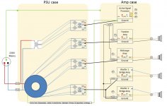
It's a better starting point except for one thing, are the woofer amps truly "bridged"? If so, each woofer should be connected between the two amp outputs, with one output "phase inverted", and no speaker terminals grounded.
Mike
Yes Michael, agreed and corrected
Thanks benb, I have made the changesYou have the power ground, the heavy wire between the two bridge amps, and you've also got the signal ground, going between a bridge amp to the ground connection further up, then back down to the other bridge amp. Since the two bridge amps will (presumably) be next to each other, and there will be a short (as in a couple of inches) 14-gauge wire between the grounds of these two amps, you can remove one of the signal grounds, or at least have them run directly side-by-side from the common signal ground to the direct vicinity of the amps.
Yes, please ignore the rectifier connections, it is only a block diagramA couple more points about the diagram - you show each power supply with two bridges, but the way they are shown connected wrong. I understand this is more of a "block diagram" but I find it bothersome that they're not correct.
Yes, that's also corrected...Furthermore, the top power supply shows a center-tapped secondary connected. This cannot use two bridges, it uses only one bridge. The standard connection has the bridge + and - output be the power supply + and - outputs, and the center tap connect to ground.

I have also added a green line connecting the transformer to audio ground. This connects the electrostatic shield between primary and secondary windings in the transformer to the audio ground. Purpose of this shield is to reduce common mode noise which is otherwise coupled through the transformer capacitively.
- Status
- Not open for further replies.