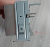
It's a bit tricky to mount he LM's without bending it's pins a bit, or mount the PCB a bit diagonally , because the base of the heatsink were the original Transistors were mounted isn't flat but at an angle. I could file it flat and sand paper it ( very fine grit up to 3000 ) .
Or I could mount them in the middle, where the heatsink is flat, the part on the bottom it's thicker tho.
Or I could mount them in the middle, where the heatsink is flat, the part on the bottom it's thicker tho.
Attachments
You don't HAVE TO write in ALL CAPITAL LETTERS to be UNDERSTOOD. Formatting like bold and italic is preferred for emphasis. You can even use a different colour.50 watts @ 8ohms and 100 watts @ 4 ohms > IE. an amplifier that has HIGH CURRENT CAPACITY to avoid compression.
High current capacity and high power are not synonymous. Take Jeff Rowland's approach for example. He uses six LM3886 in parallel, per channel. That'll give you a minimum of 42 A of output current per channel, but the power output is still limited by the supply voltage of the LM3886, so you'd get 50-60 W into 8 Ω at the most even though 42 A (peak) into 8 Ω would be a tad over 7 kW if my math is right.
Different strokes for different folks. Some like high-efficiency drivers. They need amps with an ultra-low noise floor and only need a few watt at the most to get sufficient SPL. Others try to create night club SPLs in their large living rooms. That requires power no matter how you slice it. Most of us likely fall between the two and for us the LM3886 or two of them in parallel work well.
Tom

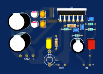
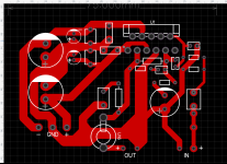
You don't work from a schematic? Creating layouts by drawing polygons in the layout tool without having a schematic (and netlist to connect schematic and layout) is a sketchy practice.This is what I did so far .
* forgot the Mute circuit
Tom
I did look both at the datasheet and schematic here, I just forgot about the mute circuit at that moment. Yes , I did not use a schematic in the pcb program , netlist, ratlines, etc. For rather simple PCB's like this, I place the component footprint , and go from there , arrange the components , by schematic.You don't work from a schematic? Creating layouts by drawing polygons in the layout tool without having a schematic (and netlist to connect schematic and layout) is a sketchy practice.
Tom
A bad habit , maybe because I used to do the PCB's on 1x1mm paper with a pencil ( old times ).
Also the program that I use is rather limited ( EasyEDA) . I should " evolve" and do it proper , export the files and have the PCB's made by a company that ships them to your door. A nicer way would be photosensitive PCBs and have nicer results or again have them made by a company.
I still like to draw them with a paint marker , that method is outdated tho.
Yes the proper way I should learn to do is what you said.
I used to draw PCBs by hand as well. I then moved to a CAD system and was drawing PCBs from paper schematics. Working in the semiconductor industry where a wiring mistake can cost $1M to fix and delay the project by months (-> $$) changed me permanently. I won't use any tools that don't allow for DRC and LVS (layout versus schematic) checks.
Modern tools like KiCAD are free and good. They support a production workflow and it requires no effort to follow that workflow.
I too used to etch my own boards. I actually had a pretty nice setup with photo-resistive boards, UV lamp for exposure, etc. when I was in college. But these days I let outfits like OSH Park, PCBWay, or the like make my prototype boards. My production boards are made in Canada. I don't miss the mess, the ruined clothes, or having to dispose of nasty chemicals. Having the pros make the boards also makes it possible to use parts with finer pin pitch.
That said, there is some satisfaction in the ability to turn a board in a few hours in the garage.
Tom
Tom, I tried your suggestions and put 470pf in front of the ferrite but there was no improvement. I ground my aluminum can and there was no improvement. It's caused by something, but what?Cry? Pray? Drink more? Or ... I dunno? ... add 470 pF to ground after the ferrite bead? 🙂
Switch sparks emit pretty wide-band RF. You need to prevent that from entering the amp. The way to do that is by a) avoiding large antennas and b) filtering.
Large antennas can be avoided to some extent by putting the amp in a metal enclosure and connecting to it with shielded cables. If you still have the amp as a prototype on a piece of plywood, I wouldn't worry overly about RFI. If you still have issues after putting into a chassis, there might be some action needed.
I was told by a commercial manufacturer that they had to resort to LC filtering on amp inputs to pass the EMC requirements for some of the European standards. That's what I do on my amps. The ones made with SMD components all have LC (or, rather, LRC) filtering. I use the R to tame the Q of the LC filter so it doesn't cause peaking in the frequency response.
I usually aim for >40 dB attenuation at 8-10 MHz. I think I got that from a note on Siegfried Linkwitz's schematics for the LXmini amp/XO. He used three RCs, but I found that too noisy, so I switched to LRC instead.
Tom
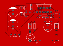
This is my GND design:
Do you have the amp in a closed enclosure or is the enclosure open? If it's open or if there are large non-conductive openings in the enclosure RF can get in that way. It can also get in through input and output cables.Tom, I tried your suggestions and put 470pf in front of the ferrite but there was no improvement. I ground my aluminum can and there was no improvement. It's caused by something, but what?
Tom
The problem persists on my tom protected box. It's even slightly affected by the planes passing over my house. 😀

Cool! Maybe if you tune it right you can get to talk to ghosts of past inhabitants of your house... 🙂
Well, that's odd. I'd start by making sure that you have proper decoupling on the LM3886. 1000 uF || 22 uF || 1 uF X7R on each rail. You already have the RFI filter on the input, so you should be good there. It still wouldn't hurt to add some ferrite clamps on the cables right where they enter the enclosure. Or wind the input wiring and output wiring on a ferrite core of some sort.
The only time I've ever had RF enter an LM3886 amp that I made was when I was playing around with a point-to-point setup. All my other builds have been resistant to RF.

Tom
Well, that's odd. I'd start by making sure that you have proper decoupling on the LM3886. 1000 uF || 22 uF || 1 uF X7R on each rail. You already have the RFI filter on the input, so you should be good there. It still wouldn't hurt to add some ferrite clamps on the cables right where they enter the enclosure. Or wind the input wiring and output wiring on a ferrite core of some sort.
The only time I've ever had RF enter an LM3886 amp that I made was when I was playing around with a point-to-point setup. All my other builds have been resistant to RF.
Tom
YES > I have been 'pulled up' regarding my writing style before. I will just have to try and do better in the future 😕You don't HAVE TO write in ALL CAPITAL LETTERS to be UNDERSTOOD. Formatting like bold and italic is preferred for emphasis. You can even use a different colour.
High current capacity and high power are not synonymous. Take Jeff Rowland's approach for example. He uses six LM3886 in parallel, per channel. That'll give you a minimum of 42 A of output current per channel, but the power output is still limited by the supply voltage of the LM3886, so you'd get 50-60 W into 8 Ω at the most even though 42 A (peak) into 8 Ω would be a tad over 7 kW if my math is right.
Different strokes for different folks. Some like high-efficiency drivers. They need amps with an ultra-low noise floor and only need a few watt at the most to get sufficient SPL. Others try to create night club SPLs in their large living rooms. That requires power no matter how you slice it. Most of us likely fall between the two and for us the LM3886 or two of them in parallel work well.
Tom
Regarding some of your comments, it is not just the current capacity that is available into a fixed 8ohm impedance/load because
speakers don't have flat impedance (with the rare exception of a Magnepan style speaker). The efficiency of a speaker really has nothing to do with it.
If you had a speaker that ranged from 4ohms to 12ohms across the spectrum, you would immediately realize the importance of current capacity.
This is simply realized by understanding Ohms Law. The ideal scenario is 'infinite' current capacity, so the voltage output of an amp. remains the same
regardless of load.
With a current limited amplifier, audio output of your speakers will drop @ low impedance and rise @ high impedance >
creating frequency dependent compression. IE. the more the current is limited, the more your speakers sound like their impedance curve.
PS.
This is why I have a power amp. that quadruples its power into 2ohms vs 8ohms. I am essentially 'impedance immune'.
This is why I have a power amp. that quadruples its power into 2ohms vs 8ohms. I am essentially 'impedance immune'.
Um. No.If you had a speaker that ranged from 4ohms to 12ohms across the spectrum, you would immediately realize the importance of current capacity.
The "limitations" you are talking about only exist if you drive the amp to clipping, which few of us ever do.
If you power an LM3886 from ±30 V you'll get 65 W into 4 Ω and about 40 W into 8 Ω. So if you dial up the output voltage of the LM3886 until you get 65 W into 4 Ω, that amp will power any load with an impedance of 4 Ω or greater, including the "12 Ω that dips to 4 Ω" speaker that you invented, without clipping.
Are you suggesting that I don't understand Ohm's Law?This is simply realized by understanding Ohms Law.
No again. There is no need for infinite current. That follows from Ohm's Law as well.The ideal scenario is 'infinite' current capacity, so the voltage output of an amp. remains the same
regardless of load.
An amplifier will need to be able to provide a minimum output current of VCC/Rload to prevent current limiting. So if your amp runs on, say, ±56 V, it will need to be able to supply 56/4 = 14 A of output current to drive a 4 Ω impedance to clipping. That's Ohm's Law, right?
Only if you operate the amplifier at its current limit, i.e., with the amplifier hard clipping. Nudge the volume control back a bit and everything falls back into place.With a current limited amplifier, audio output of your speakers will drop @ low impedance and rise @ high impedance >
creating frequency dependent compression. IE. the more the current is limited, the more your speakers sound like their impedance curve.
Tom
1. Clipping has nothing to do with my point.
2. There is something that you don't seem to understand about Ohms Law.
3. I wrote "infinite" ( as a scenario ) in inverted commers because we know that is not practical fact, but an ideal. I do know!
4. Once again ... clipping has nothing to do with 'pre-clipping' current capacity.
(5) You are a little confused !
- Home
- Amplifiers
- Chip Amps
- LM3886 A great little Amplifier