Where in the schematic is that inductor from your picture?
Power ground and signal ground should connect somehow.
Power ground and signal ground should connect somehow.

"Signal GND and Power GND are combined in capacitors. Some funny scheme."
I don't understand that.
I don't understand that.
Cry? Pray? Drink more? Or ... I dunno? ... add 470 pF to ground after the ferrite bead? 🙂I used the same filter but not the 470pf. What do you think I should do?
Switch sparks emit pretty wide-band RF. You need to prevent that from entering the amp. The way to do that is by a) avoiding large antennas and b) filtering.
Large antennas can be avoided to some extent by putting the amp in a metal enclosure and connecting to it with shielded cables. If you still have the amp as a prototype on a piece of plywood, I wouldn't worry overly about RFI. If you still have issues after putting into a chassis, there might be some action needed.
I was told by a commercial manufacturer that they had to resort to LC filtering on amp inputs to pass the EMC requirements for some of the European standards. That's what I do on my amps. The ones made with SMD components all have LC (or, rather, LRC) filtering. I use the R to tame the Q of the LC filter so it doesn't cause peaking in the frequency response.
I usually aim for >40 dB attenuation at 8-10 MHz. I think I got that from a note on Siegfried Linkwitz's schematics for the LXmini amp/XO. He used three RCs, but I found that too noisy, so I switched to LRC instead.
Tom
Yeah. It should be in series with either C1 or R1. Sounds like that's how you have it.The inductor is connected in series to the audio signal 😀
You'd get better performance (lower THD) if you connected SIG_GND to the Speaker(-) output (which is also connected to ground).Signal GND and Power GND are combined in capacitors.
The wire connecting SIG_GND is an antenna, by the way.
Is the LM3886 board exactly as shown in the schematic? If so, you need to add at least 470 uF on each supply rail. I prefer 1000 uF.
Tom
I do prefer the sound of modified circuit. Here is simple instruction for those interested. It worked for me in the past.
i have been working on a20 preamp
started work on MTM with peerless mids and hiquphon tweeter
both still work in progress
i have finished f1j amp, and will make another, this time just f1
since I like the sound of transconductance amps, i was experimenting with various chip amps, since they are cheap and available
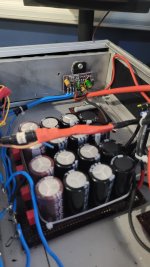
here is my first prototype conversion of XY LM3886 chip amp
i will describe step by step procedure if anyone is interested in doing so
the sound is much more musical after the conversion
started work on MTM with peerless mids and hiquphon tweeter
both still work in progress
i have finished f1j amp, and will make another, this time just f1
since I like the sound of transconductance amps, i was experimenting with various chip amps, since they are cheap and available
here is my first prototype conversion of XY LM3886 chip amp
i will describe step by step procedure if anyone is interested in doing so
the sound is much more musical after the conversion
stay safe my friends!
here are some projects i am working on at home
first i got some old vifa midranges back from a friend, and I got small dayton amt to mate them with
vifa 13wh-00-08 is somewhat special midrange, free of the breakup grunge, even the ones i got are old, they still measure nice
here are some pics from the build, work in progress
may go active!
- adason
- Replies: 210
- Forum: The Lounge
http://edsaudiopages.blogspot.com/2021/07/how-much-amplifier-power-do-you-need.html[ just a passing thought ]
I find it quite strange & interesting how many people are interested in LOW POWER AMPLIFIERS 🙄
@Mister Audio, LM3886 is not low power amplifier.
3-5 watts per chanel amplifier is low power, yet with sensitive speakers it still can be plenty.
3-5 watts per chanel amplifier is low power, yet with sensitive speakers it still can be plenty.
YES ...It is a question of your needs.
Most people just need fairly low power to get the normal level of loudspeakers.
Sometimes I like to hear music with dynamics that actually kick & shake me !
50 watts @ 8ohms and 100 watts @ 4 ohms > IE. an amplifier that has HIGH CURRENT CAPACITY to avoid compression.What is the upper limit for "low power"?
PS.
Some people don't realize that amps. that can't double power from 8 ohms to 4 ohms actually introduce AUDIO COMPRSSION 😎
Some people don't realize that amps. that can't double power from 8 ohms to 4 ohms actually introduce AUDIO COMPRSSION 😎
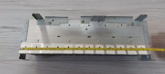
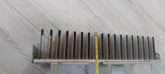
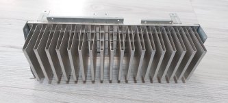
Would this heatsink be enough for two LM's ? . ( thinking about 24 or 28 Vdc Rails . ) I dont really like this design ( not made from one piece , having the " fins " soldered to the aluminium sheet. ) Anyway. this is what I have at hand , if not good enough I'll buy something better.
Attachments

- Home
- Amplifiers
- Chip Amps
- LM3886 A great little Amplifier