How can my Body be 1/2 V different in potential to the air around it
Don’t try to build a case out of this. Just consider the difference in potential between your and your wife’s body. Some hundred volts or so? 😉
George
George, way too high a potential difference at times 😱 but some contact usually sorts that out 😉
Thanks Andrew 🙂 I went and bought an IEC socket with EMI filter in it today. I'm just trying to work out the layout of the prototype chassis. They only had the one type, a 6A one. After googling it and finding the datasheet I should have tried to get a 1A one. The lower power ones attenuation is a lot better. Oh well I need one on my mosfet amp so may find another and replace when I do the final chassis and put this one into the mosfet amp.
Tony.
Last edited:
I bought a few batches on Ebay.
I have a stock of 1A, 3A, 6A, switchable, fused, etc.
I refuse to pay for one at a time, when I know what I am like.
I have a stock of 1A, 3A, 6A, switchable, fused, etc.
I refuse to pay for one at a time, when I know what I am like.
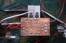
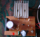
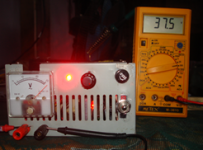
Here is my Power Supply Adjuster Experment 3 amps transformer but i used LM317 instead of LM350 0-30 volts but exceeded in 37.5volts


An externally hosted image should be here but it was not working when we last tested it.
i don't know why my pics was remove.. but i attached my pics here,,, i think you going to download it... just like what i've post a while ago... i used LM317 instead of LM350 because LM350 is designed for 3 amps. while the LM317 is Designed by 1 amp... so is doubled it in order to avoid Over Heated..
Attachments

After googling it and finding the datasheet I should have tried to get a 1A one. The lower power ones attenuation is a lot better.
Indeed.
Also Schaffner that I typically use have product lines with different attenuation ratings (normal, good, high, very high or something along those lines) and other features (e.g. with earth choke or w/o) which differentiate IECs with the same current ratings.
So, not even all Schaffner filtered 1A IECs are created equal. 🙂
Thanks, I found a source of Schaffner here in aus at reasonable prices 🙂 I shouldn't have been so hasty to go out and get one.... the datasheet doesn't seem to say what the difference is between the one with a bleed resistor and one with out (performance wise). The fn9244-1-06 seems to fit the bill nicely. I'm guessing that the bleed resistor may improve rejection at certain frequencies. http://www.schaffner.com/components/en/_pdf/Datasheet%20FN9244%20e%20103.pdf
Tony.
Tony.
I haven't read the whole thread but I think I've got the gist of it and I would like to add a little advice on scopes and how to NOT pick up stray noise. I have to look for small signals immersed in SMPS noise at work.........
1. You have to have an extremely short scope probe earth lead. The usual few inches acts as a nice aerial. We regularly use tip & ring, i.e. tinned copper wire twisted round the probe shield so the earth lead is about 1cm long max.
2. Wind the scope lead at the scope end a few turns through a ferrite toroid. It greatly reduces common-mode pickup from external sources without affecting the real signal at all (I've tested this!). Same with coax leads if that's what you're using. One toroid each end is even better if there's enough lead length.
Apologies if you're already doing all this.
Last edited:
thanks for the tips sbrads!! one of my scope probes I can probably do the short earth wire thing with but the other one has an approx 25cm earth lead and is moulded so can't be changed without cutting it. I think I have a small torriod core in my junk box too 🙂
Tony.
Tony.
The fn9244-1-06 seems to fit the bill nicely. I'm guessing that the bleed resistor may improve rejection at certain frequencies.
Yeap, that's the line I've been using.
Also check FN9244E-1-06 - though I bought the last one last night from Mouser. 😱
They'll have more in stock in 10 days or so.
hmm that's nice and not too much more expensive either. Thanks! I'll be ordering from a place in aus, and they have 26 in stock 🙂 though they don't seem to have any 3A ones though (for another project).
Tony.
Tony.
OK so tonight I did some more measurements in the case with the IEC filter connected. The results are much better 🙂
I tracked the weird waveform (in post 92) down to the spare PC (or it's monitor) So I know to make sure it is off if I am doing any measurements.
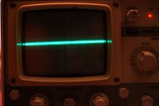
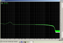
First pic is of the output of the positive rail. 2mV/div 1ms/div
Second pic left is +10V rail right is -10V rail recorded in audacity, 10X gain on the preamp. the dreaded 50Hz anomaly is back though, but can be ignored, its probably an earth loop between the PS and the PC.
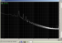
Third pic is taken on the 3r3 resistor at the output of the second cap. This is to get a reference point for the pc measurements.
Fourth pic is the spectrum on the pc for the same point as the thrid pic. 10X gain on the preamp. So 3mV p2p is about -48db on the spectrum.
Overall I'm pretty pleased with these results 🙂 though I will have to take some more with a real load. The built in pre load resistors only draw about 38mA.
Tony.
I tracked the weird waveform (in post 92) down to the spare PC (or it's monitor) So I know to make sure it is off if I am doing any measurements.
First pic is of the output of the positive rail. 2mV/div 1ms/div
Second pic left is +10V rail right is -10V rail recorded in audacity, 10X gain on the preamp. the dreaded 50Hz anomaly is back though, but can be ignored, its probably an earth loop between the PS and the PC.
Third pic is taken on the 3r3 resistor at the output of the second cap. This is to get a reference point for the pc measurements.
Fourth pic is the spectrum on the pc for the same point as the thrid pic. 10X gain on the preamp. So 3mV p2p is about -48db on the spectrum.
Overall I'm pretty pleased with these results 🙂 though I will have to take some more with a real load. The built in pre load resistors only draw about 38mA.
Tony.
Attachments

Last edited:
Tony, would you mind taking some more measurements? ARTA Download - this software should help you. It would be also intersting to see loopback measurement of your soundcard.
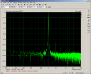
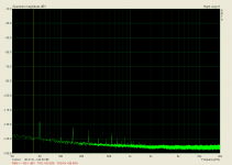
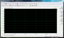
Hi Dunwenbleidd which measurements would you like? Attached are loopback measurements done in ARTA (I have 1.7.0 latest is 1.7.1)
1st is spectrum analyser mode.
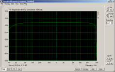
2nd is an fr plot.
I set the levels using holm impulse to the highest reading I could get without it telling me it detected digital clipping.
I'm not sure how I can use ARTA for doing measurements of the PS though 🙂
Tony.
1st is spectrum analyser mode.
2nd is an fr plot.
I set the levels using holm impulse to the highest reading I could get without it telling me it detected digital clipping.
I'm not sure how I can use ARTA for doing measurements of the PS though 🙂
Tony.
Attachments
It's just the same as measuring in loopback. A little example follows - LM317 with Vbe multiplier. Maybe I've made a mistake somewhere, but I have calculated that it shows 5,6uV (at 50Hz)... That doesn't seem quite possible with such a simple design... 😕
Tomáš
Tomáš
Attachments
- Status
- Not open for further replies.
- Home
- Amplifiers
- Power Supplies
- LM317 experiments and measurements