Tony, the 50Hz is most likely not a function of the reg per se, but of field pickup or grounds. The difference between in and out pickup may well be an impedance question. I think you need to sort out the layout issues- it doesn't have to be pretty or neat, but at these minuscule levels, it has to be correct.
Unless you're using a half wave rectifier, there shouldn't be any 50 Hz on the raw supply. That's a clue for you.
Unless you're using a half wave rectifier, there shouldn't be any 50 Hz on the raw supply. That's a clue for you.
Tomorrow, I hope to discuss a little about the “differential to single ended converter”
Tony and all.
I thought to open a new thread there http://www.diyaudio.com/forums/equipment-tools/189545-implementing-y-out-oscilloscope.html#post2581456
for to let the discussion about LM317 run smoothly here.
Regards
George
Yes I think you are right SY 🙂 I just went back and looked at previous measurements, the 50Hz hump is almost identical to the that in pic two post 48, which was of the preamp only (scope probe shorted) before and after the mods.... It is almost certainly coming from the preamp.... It is just kinda weird... I tried hooking up the chassis of the transformer case to the earth wire of the PS and man did I get some noise then! 50 hz was at 0db and the noise floor was at about -6db!! severe ground loop with the pc...
and thanks George your a star! 🙂
Tony.
and thanks George your a star! 🙂
Tony.
Well I haven't posted any more measurements because I wanted to get to the bottom of my 50Hz problem (which is proving to be rather difficult to track down. I also smoked the load resistor on the -ve side of the power-supply (and haven't checked if everything is alright. I decided I needed a break from it.
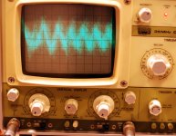
This afternoon I decided I'd try and get a baseline for the levels. Unfortunately that has lead to other issues. The output on my sound card (both actually) seems to be very noisy (strange considering they measure well with RMAA). If I plug the output of the card directly into my scope the noise levels are around 120mV p2p 😱 for the audigy and around 20mV p2p for the on board sound. Both appear to be some sort of high frequency oscilation (or oscilations) The oscilation on the onboard sound card seems to be maybe 3 fundamental frequencies, the audigy seems to be maybe 10-20.
It might be time I bit the bullet and bought a nice USB sound card. This would also have the advantage that I could use it with my laptop and run it off battery, completely eliminating the possibility of earth loops with the mains, as well as 50 Hz contamination. I will be back with more once I have things sorted 😉
1st pic is the audigy scope settings are 20mV/div and 5uS / division
2nd pic is the onboard sound. scope 5mv/div and 1uS/div
I was planning on trying to get something that produced a 10mV p2p 50 hz sine wave and then put that through the 10X preamp to see what I got to get some absolute levels, but this somewhat put me off 😉
Tony.
Attachments

...that is PC noise injected into the ground loop.
You need a floating ground 'scope when playing with PCs.
I use an isolation transformer on a regular 'scope.
Yes, I know, this is NOT recommended!, this is not NOT safe!, do NOT do it!:
Tektronix: Technical Brief > Floating Oscilloscope Measurements ... And Operator Protection : Part 3
Used to have an audigy 2. IIRC the noise was <2mV, difficult to see on the 'scope with a 10x probe.
RMAA may measure OK regardless, as this noise is mostly outside the measured bandwidth. Or you did not have the 'scope connected during the RMAA tests?
Hi Discrete,
if the "equipment" being measured is "powered" via an isolating transformer, then the "equipment" is effectively "floating".
If the oscilloscope is ground via it's PE connection and the oscilloscope probe grounding tip/wire is connected to the "equipment" then the equipment is no longer floating and has moved, voltage wise, towards the probe tip voltage, then the equipment and the oscilloscope are both safe to touch.
If the probe is disconnected, the oscilloscope and floating equipment are both safe to touch.
If this method "safe" ?
Can operator safety be improved?
Thanks discrete, I'd wondered about problems with ground loops with the PC. The thing I thought was a bit odd was that the audigy's noise seems much worse than the built in sound card, but on rmaa the noise floor is actually better on the audigy. Scope was not connected for rmaa tests, just a 10cm loopback cable.
I assume that the card itself picks up internal noise from other components of the pc and then injects into the ground.. I might try moving the card around (although I only have a a few pci slots to try).
Do you think a laptop with a USB soundcard would have less of a problem?
Tony.
I assume that the card itself picks up internal noise from other components of the pc and then injects into the ground.. I might try moving the card around (although I only have a a few pci slots to try).
Do you think a laptop with a USB soundcard would have less of a problem?
Tony.
I assume that the card itself picks up internal noise from other components of the pc and then injects into the ground.
Much more likely is that you have a ground loop somewhere in the analog domain- between power supply, computer, test leads, scope, soundcard...
One of the nice features of Pete Millett's sound card interface as compared to the one I was previously using is that the power supply is isolated from line frequencies. That made a real difference in the ease of getting my test setup optimized for each experiment.
Hi Discrete,
if the "equipment" being measured is "powered" via an isolating transformer, then the "equipment" is effectively "floating".
If the oscilloscope is ground via it's PE connection and the oscilloscope probe grounding tip/wire is connected to the "equipment" then the equipment is no longer floating and has moved, voltage wise, towards the probe tip voltage, then the equipment and the oscilloscope are both safe to touch.
If the probe is disconnected, the oscilloscope and floating equipment are both safe to touch.
If this method "safe" ?
Can operator safety be improved?
Hi Andrew,
I may be wrong, but it seems to be 6 or 1/2 a dozen....
Either the equipment or the 'scope is not solidly grounded at some stage, especially in the case of something like a PC.
I would also not depend on the typical alligator clip found on 'scope probes for a safety ground.
Hi D,
an amplifier powered via an isolating transformer is "safe".
The PE has not been defeated. The PE is still operative in the area that must be protected
There is no way for the Mains LIVE or Neutral terminals to contact any part of the amplifier. Thus the amplifier does not need a separate PE, it does not have Mains inside it.
that's why I inserted my third paragraph.If the probe is disconnected, the oscilloscope and floating equipment are both safe to touch.
Hi Sy, funny you should mention Pete's sound card interface, I'd seen it before and was just going over the thread again! 🙂
I was toying with the idea of looking into opto-isolators the other day, no idea if it is feasible though, as I don't have any clue as to their capabilities.
Tony.
I was toying with the idea of looking into opto-isolators the other day, no idea if it is feasible though, as I don't have any clue as to their capabilities.
Tony.
Do you think a laptop with a USB soundcard would have less of a problem?
Tony.
These days I use one of the new EMU-0204 USB audio interfaces.
The EMU is powered from USB and I still see ground loop issues doing anything more complicated than simple loopback tests (EMU to EMU).
It does have ground-break switches on the two analog input channels. And these do make a difference when testing a third device.
For a pre-amp for example the best result was lifting the pre-amp signal ground and closing the EMU ground.
Laptop on battery power should help, depending on where the USB audio interface is powered from and the quality of the laptop inverters.
Hi D,
an amplifier powered via an isolating transformer is "safe".
The PE has not been defeated. The PE is still operative in the area that must be protected
There is no way for the Mains LIVE or Neutral terminals to contact any part of the amplifier. Thus the amplifier does not need a separate PE, it does not have Mains inside it.that's why I inserted my third paragraph.
Same for the 'scope.
Isolating the 'scopes at university was a common practice (this was many years ago though), depending on what you were working on.
Still Tektronix strongly advises against this and I can see it being frowned upon in a production setting.
Yet, as you say, it is 'safe'.
I do it, but I understand and accept the implications.
Cannot recommend it for casual users...
Isolation transformer powering of the scope is completely different.
Float the scope and connect it to a high voltage part of the amplifier and the scope moves to the high voltage. Touch any metal on the scope or scope probe and ????
This is clearly unsafe and why TEK clearly show that their equipment must never be powered by isolation transformer.
Float the scope and connect it to a high voltage part of the amplifier and the scope moves to the high voltage. Touch any metal on the scope or scope probe and ????
This is clearly unsafe and why TEK clearly show that their equipment must never be powered by isolation transformer.
Tony: Isolating the power supply is easy. And usually, that is all you have to do to get isolation from the line.
Isolation transformer powering of the scope is completely different.
Float the scope and connect it to a high voltage part of the amplifier and the scope moves to the high voltage. Touch any metal on the scope or scope probe and ????
This is clearly unsafe and why TEK clearly show that their equipment must never be powered by isolation transformer.
Good point.
Last edited:
Hmmm I'm wondering whether the comments on the noise are the original 50Hz problem or the latest high frequency noise problem I've noticed. I have a suspicion Discrete is talking about the high frequency noise, and SY about the 50Hz?
The original 50 Hz problem there is no ground loop (that I am aware of) as the preamp ran off a 12 V battery, and the PS 0V was not connected to safety earth for the tests (when it was there was a massive earth loop problem with the noise floor being around -6db at low frequencies!!!
The high frequency noise however there is almost certainly a ground loop between the scope and the PC, now that I think of it. When doing amp measurements I have to have a low ohm resistor in series with the earth line of the SC preamp input to suppress the earth loop issues. They are permanently attached to my dummy loads.... I probably should try the same for checking the output of the SC...
Discrete, I hadn't even considered that the laptop may have inverters in it. I figured that the batteries would generally be 14V or higher and that the highest voltage required should be 12V.... so regulators would be all that was present??
Tony.
Hmmm I'm wondering whether the comments on the noise are the original 50Hz problem or the latest high frequency noise problem I've noticed. I have a suspicion Discrete is talking about the high frequency noise, and SY about the 50Hz?
Discrete, I hadn't even considered that the laptop may have inverters in it. I figured that the batteries would generally be 14V or higher and that the highest voltage required should be 12V.... so regulators would be all that was present??
Tony.
I saw both 50 (60) Hz with harmonics and HF.
ARTA also showed a component around 44 kHz (coincidence?), that disappears when I play with the grounds.
Laptop will have step up/step down switchers for reasons of efficiency and heat dissipation.
wintermute,
I built my own frontend for a soundcard, with some more connectors, and a relay so I can "mute" the input. When I do that, all the 50/100/150Hz lines disappear and all I see is the remaining noise floor of the amplifier + soundcard. As soon as the "mute" is off (with nothing connected to the inputs except a 600 Ohm resistor), 50Hz re-appear..... it must be the electromagnetic field in the lab, powering from a battery didnt change anything. I remember Scott Wurcer commenting in another thread about noise measurements on FETs that he had to use double shielding, and put the measurement box in the middle of the room where the field was at its lowest, i.e. the furthest away from any power line, lamp, other equipment, what have you...
just my two cents...
Thanks hesener. the preamp is in a plastic box (was a kit) so that is not providing any sheilding at all (and is probably something I should address as a matter of course, a diecast aluminium box should be an improvement). I did try moving to the middle of the room, but I think perhaps I should try moving out onto the balcony. There may be fields coming from the unit above.
I've got some rca's configured as a short and some others with 1K resistors I will try those on the inputs to the preamp (with my bnc to rca adaptors). Will be interesting to compare the shorted one with the result with the shorted scope probe, thanks for the idea! 🙂
Tony.
I've got some rca's configured as a short and some others with 1K resistors I will try those on the inputs to the preamp (with my bnc to rca adaptors). Will be interesting to compare the shorted one with the result with the shorted scope probe, thanks for the idea! 🙂
Tony.
- Status
- Not open for further replies.
- Home
- Amplifiers
- Power Supplies
- LM317 experiments and measurements