Io credo che i componenti sono troppo lontano del LM1875, tutti i resistanze e condensatore deve essere presso delle perni (1 a 5)
Scusate me ma ho dimenticato presso tutto mio Italiano.. 😀
I believe the components are too far away from LM1875, all of the resistors and capacitors must be close to the pins.
Please excuse me I have forgotten most of my Italian..
Ciao
Scusate me ma ho dimenticato presso tutto mio Italiano.. 😀
I believe the components are too far away from LM1875, all of the resistors and capacitors must be close to the pins.
Please excuse me I have forgotten most of my Italian..
Ciao
hello kevinkr, thanks for your intervention, can you post me a diagram to make me understand?
Mooly, I'm going to do that check and let you know.
Mooly, I'm going to do that check and let you know.
Hi
This is TDA2030 with same pinout and function as LM1875.
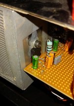
As you can see, my entire layout is fitted to within two veroboard holes. Longest distance between any pin and component is less than 3mm. All the resistors are surface mount types directly soldered to the pins under the board.
While your layout looks very pretty, the functionality depends on components being close to the chip. Even when using leaded components you can get things pretty tight. If not, you will face instability and oscillation.
Actual wires have resistance and reactive mechanisms that impose themselves on the actual connection, thus important to keep them close. When a designer draws a connection he assumes zero resistance, zero inductance and zero capacitance. Real wires are none of those things.
This is TDA2030 with same pinout and function as LM1875.
As you can see, my entire layout is fitted to within two veroboard holes. Longest distance between any pin and component is less than 3mm. All the resistors are surface mount types directly soldered to the pins under the board.
While your layout looks very pretty, the functionality depends on components being close to the chip. Even when using leaded components you can get things pretty tight. If not, you will face instability and oscillation.
Actual wires have resistance and reactive mechanisms that impose themselves on the actual connection, thus important to keep them close. When a designer draws a connection he assumes zero resistance, zero inductance and zero capacitance. Real wires are none of those things.
Attachments
ok, thanks sangram.
when the chips are not powered the voltage of pin1,2e4 is zero, when they are powered I can hardly test them because the temperature rises immediately and they become hot, I have already burned several in these days, I used a 30-0-30 toroidal and then a 24-0-24
when the chips are not powered the voltage of pin1,2e4 is zero, when they are powered I can hardly test them because the temperature rises immediately and they become hot, I have already burned several in these days, I used a 30-0-30 toroidal and then a 24-0-24
Those toroid voltage are much to high for an LM1875. You want approximately -/+25 volts DC rails and so an 18-0-18 toroid is what is needed. No higher.
Your 30v toroid will be giving nearly -/+ 45 volts which will destroy the chips. The 24v one will give nearly -/+35 volts which is still over the devices rating.
Use a DBT (dim bulb tester) with a suitable transformer to limit current.
Your 30v toroid will be giving nearly -/+ 45 volts which will destroy the chips. The 24v one will give nearly -/+35 volts which is still over the devices rating.
Use a DBT (dim bulb tester) with a suitable transformer to limit current.
+1. You have to use a 15-0-15V transformer, maximum. I have used up to 17V secondary voltage with no ill effect but the chip does get warm. The sweet spot for the chip is between 13 and 16V secondaries for about 20 to 23V DC.
.thanks guys, then i think i have solved it.va in thermal protection right? what mistake did i make obviously i am a beginner and beginner's mistake
One mistake are those transformer voltages. The chip has an absolute maximum rating of 60 volts (so -/+30) but it is an absolute maximum and certainly not a recommended operating voltage.
You need to run it all up on a lower voltage current limited supply, so a lower voltage transformer and low wattage mains bulb in the primary circuit.
You need to run it all up on a lower voltage current limited supply, so a lower voltage transformer and low wattage mains bulb in the primary circuit.
Excellent Italian!!!! 😀Io credo che i componenti sono troppo lontano del LM1875, tutti i resistanze e condensatore deve essere presso delle perni (1 a 5)
Please excuse me I have forgotten most of my Italian..
Ciao
EDIT:
WAY too high.I used a 30-0-30 toroidal and then a 24-0-24
Multiply those AC voltages by 1.42 to get scary DC voltages.
Follow above suggestions.
And try to make a smallcompact amp as suggested, even on Veroboard.
Those amplifiers have *excellent* high frequency response ... so much so (hundreds of kilohertz and even a couple MHz) plus a lot of internal gain plus lots of feedback to keep distortion very low.
Excellent very accurate sound but that makes layout critical.
Last edited:
.thanks guys, then i think i have solved it.va in thermal protection right? what mistake did i make obviously i am a beginner and beginner's mistake
Chip will probably be permanently damaged with 30V Ac secondary, you will probably need new chips.
Lm1875 can sound really sublime. Application list schematics is ok, but inverting schematics sounds better. Transconductance even better. I much preffer the sound of lm1875 to that of lm3886.
I run most of my lm1875 amps on either regulated power supply of +/-15 volts, or unregulated well filtered +/-22 volts.
Good luck!
I run most of my lm1875 amps on either regulated power supply of +/-15 volts, or unregulated well filtered +/-22 volts.
Good luck!
hello, it's still me, the pain in the *** beginner, I wanted to tell you that I powered the 1875 with a 12-0-12 + -28v and the preamp
because I use a preamplifier with tone controls and 2 lt1028 opamps or others by interchanging them with the slots.
the preamp I feed it with a 9-0-9 that gives me 12.6 volts (before I used 12 volts), anyway the result is always the same faint sound and chips that heat up immediately, one in particular more than the other.
at this point it remained: only burnt and / or broken chips, what do you think?
one other thing, the metal plate on the chip is alive, you have to be absolutely sure you isolate it from the heatsink, especially if you mount two chips on the same heatsink
thanks adason, yes I isolated the chips from the heatsink with silicone sheets of thermal paste and plastic supports made especially for that purpose
Have you tried decoupling the chips as was mentioned earlier?
The chip should really have some decoupling close up to the pins. It might be worth add a small cap (say 47uF) directly between the two supply pins on each chip. Make sure the voltage rating of the cap is suitable if you try this.
- Home
- Amplifiers
- Chip Amps
- LM1875 non funziona