LM1875
Hello everyone, I'm new to the forum and I wanted to ask you for a courtesy given your experience,
could you give me a correct schematic for an amplifier with lm1875,
I'm not very experienced, but I'm trying to make one.
I followed some pattern found on the net and they don't seem to work.
I tried to find some in the forum but I couldn't.
every time I assemble one I have a problem lately
the volume was faint, in another loud noise from the speakers.
I just can't understand where I'm wrong, but I would like to start at least from a fixed point, that is a working and well tested scheme.
thank you for your kindness.
See you soon
ps this is the last pattern I followed
Tales From the Chip: LM1875 Audio Amplifier : 8 Steps (with Pictures) - Instructables...
?
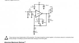
That page says
which is the opposite of what they should be. The diagram looks to be correct though.
Are you using a split (dual rail) supply as shown ?
1 - Negative Input (-IN)
2 - Positive Input (+IN)
which is the opposite of what they should be. The diagram looks to be correct though.
Are you using a split (dual rail) supply as shown ?
ciao, hello, thanks for the answer, I feed it with alternately, to try, with a toroidal 17.0 17-30.0.30, and linear 24.0 24,
but the result is still the same atrocious noise
but the result is still the same atrocious noise
If it is making a noise then it might be unstable or oscillating.
I assume all your power supplies are producing clean DC. For example the 17-0-17 toroidal needs a rectifier and reservoir capacitors to produce a clean -24, 0, +24 volt supply.
The layout and how you wire it all up is very very important. If you get this wrong then it will be unstable.
I assume all your power supplies are producing clean DC. For example the 17-0-17 toroidal needs a rectifier and reservoir capacitors to produce a clean -24, 0, +24 volt supply.
The layout and how you wire it all up is very very important. If you get this wrong then it will be unstable.
but it is not only with that scheme that gives me problems, it is also with other schemes, I will have used about ten, and the result is always the same
yes I know this is the national scheme I think? I should have used this too, you say it's the best model to follow?
Its a model that should work correctly. I'm not sure there is any such thing as 'best' because that means different things to different people.
The data sheet diagram is correct and fully functional and should be used as a starting point.
The data sheet diagram is correct and fully functional and should be used as a starting point.
okay mooly I'll assemble one asap and let you know.
thank you for your kindness, you were very kind to answer me, see you soon, bye
thank you for your kindness, you were very kind to answer me, see you soon, bye
OK good luck 🙂
(and when you connect it all up make sure that you run the speaker return lead back to the power supply. That will prevent the high speaker currents causing possible feedback around the other parts of the circuit)
(and when you connect it all up make sure that you run the speaker return lead back to the power supply. That will prevent the high speaker currents causing possible feedback around the other parts of the circuit)
A few pictures of your build would be really helpful.
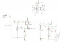
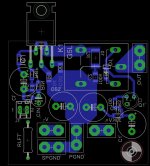
Anyway here's my schema and PCB, works pretty well. The relay is optional but avoids the very loud turn-off thump.
Edit:
I went through those links. You do not want to build this on a breadboard. At least a veroboard with tight component spacing and very short paths, as short as possible. I prefer using SMD as long as I can see them for this reason, it also simplifies layout. The 1875 is not the most stable chip at the best of times and needs babysitting. A breadboard is asking for disaster.
Attachments
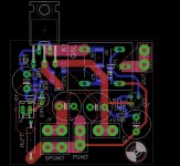

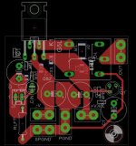
Here's some views with the top copper and bottom copper. It might be helpful to visualise the effective current paths.
In hindsight I would have liked a different way of routing the signal ground, but even this works quite well.
Attachments
OK good luck 🙂
(and when you connect it all up make sure that you run the speaker return lead back to the power supply. That will prevent the high speaker currents causing possible feedback around the other parts of the circuit)
mooly, can you please explain that link better that I didn't understand?
thank you
Please post a picture of what you actually built.
The schematic can be correct, but layout, grounding, shielding all play a big part too.
The schematic can be correct, but layout, grounding, shielding all play a big part too.
- Home
- Amplifiers
- Chip Amps
- LM1875 non funziona