inverted amp with 3,6 gain...first try
Hi
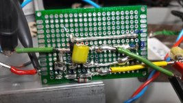
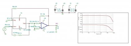
i build a inverted amp - 1 chip LM1875 genuine as in post #200 by FF. i use 2k2 and 8k1 for the gain setting. ---> 3,6 ......220µF and 220nF per rail as closed as possible (no SMD). not my best work but lets do it. the zobel 220nF/10R i use at the terminal were i connect the load (right side-not on the pic)
pic 1 board top
pic 2 board buttom - no the fb resistor is not touching the heat sink 🙂
DC offset with +/-22V is + 10,5mV
DC offest with +/-25V is + 9,4mV
test with +/-25V and 8,2R load no cap
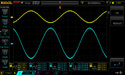
pic 3 inverted amp Gain 3,6 25V supply 8,2Rload_4,1Vrms in 1khz near clipping
pic 4 inverted amp Gain 3,6 25V supply 8,2Rload_4,1Vrms in 1khz - oscillating/clipping
frequency response:
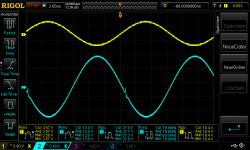
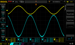
pic 5 inverted amp Gain 3,6 25V supply 8,2Rload_3,5Vrms in 10khz
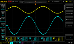
pic 6 inverted amp Gain 3,6 25V supply 8,2Rload_3,5Vrms in 20khz
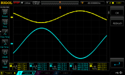
pic 7 inverted amp Gain 3,6 25V supply 8,2Rload_3,5Vrms in 30khz
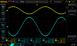
pic 8 inverted amp Gain 3,6 25V supply 8,2Rload_3,5Vrms in 50khz (small distortion visible)
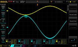
pic 9 inverted amp Gain 3,6 25V supply 8,2Rload_3,5Vrms in 80khz
pic 10 inverted amp Gain 3,6 25V supply 8,2Rload_3,5Vrms in 80khz without zobel network
chris
Hi
i build a inverted amp - 1 chip LM1875 genuine as in post #200 by FF. i use 2k2 and 8k1 for the gain setting. ---> 3,6 ......220µF and 220nF per rail as closed as possible (no SMD). not my best work but lets do it. the zobel 220nF/10R i use at the terminal were i connect the load (right side-not on the pic)
pic 1 board top
pic 2 board buttom - no the fb resistor is not touching the heat sink 🙂
DC offset with +/-22V is + 10,5mV
DC offest with +/-25V is + 9,4mV
test with +/-25V and 8,2R load no cap
pic 3 inverted amp Gain 3,6 25V supply 8,2Rload_4,1Vrms in 1khz near clipping
pic 4 inverted amp Gain 3,6 25V supply 8,2Rload_4,1Vrms in 1khz - oscillating/clipping
frequency response:
pic 5 inverted amp Gain 3,6 25V supply 8,2Rload_3,5Vrms in 10khz
pic 6 inverted amp Gain 3,6 25V supply 8,2Rload_3,5Vrms in 20khz
pic 7 inverted amp Gain 3,6 25V supply 8,2Rload_3,5Vrms in 30khz
pic 8 inverted amp Gain 3,6 25V supply 8,2Rload_3,5Vrms in 50khz (small distortion visible)
pic 9 inverted amp Gain 3,6 25V supply 8,2Rload_3,5Vrms in 80khz
pic 10 inverted amp Gain 3,6 25V supply 8,2Rload_3,5Vrms in 80khz without zobel network
chris
Attachments
-
 inverted amp gain 3,6_top.jpg141.2 KB · Views: 312
 -
 inverted amp Gain 3,6 25V supply 8,2Rload_3,5Vrms in 80khz without zobel.png47.1 KB · Views: 86
 -
 inverted amp Gain 3,6 25V supply 8,2Rload_3,5Vrms in 80khz.png47.2 KB · Views: 79
 -
 inverted amp Gain 3,6 25V supply 8,2Rload_3,5Vrms in 50khz.png43.4 KB · Views: 87
 -
 inverted amp Gain 3,6 25V supply 8,2Rload_3,5Vrms in 30khz.png44.8 KB · Views: 93
 -
 inverted amp Gain 3,6 25V supply 8,2Rload_3,5Vrms in 20khz.png45.9 KB · Views: 71
 -
 inverted amp Gain 3,6 25V supply 8,2Rload_3,5Vrms in 10khz.png46.2 KB · Views: 302
 -
 inverted amp Gain 3,6 25V supply 8,2Rload_4,2Vrms in 1khz oscillating_clipping.png46.8 KB · Views: 316
 -
 inverted amp Gain 3,6 25V supply 8,2Rload_4,1Vrms in 1khz.png50 KB · Views: 322
 -
 inverted amp gain 3,6_buttom.jpg162.5 KB · Views: 316
Last edited:
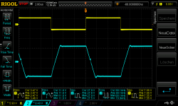
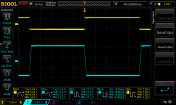
same amp with square wave:
pic 1 inverted amp Gain 3,6 25V supply 8,2Rload_3,5Vrms square in 10khz
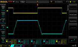
pic 2 inverted amp Gain 3,6 25V supply 8,2Rload_3,5Vrms square in 20khz
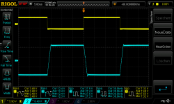
pic 3 inverted amp Gain 3,6 25V supply 8,2Rload_3,5Vrms square in 30khz
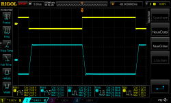
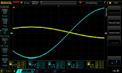
pic 4 inverted amp Gain 3,6 25V supply 8,2Rload_3,5Vrms square in 50khz
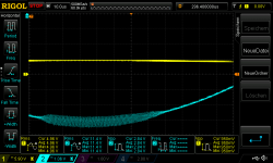
pic 5 inverted amp Gain 3,6 25V supply 8,2Rload_3,5Vrms square in 80khz
have a nice day/evening
pic 1 inverted amp Gain 3,6 25V supply 8,2Rload_3,5Vrms square in 10khz
pic 2 inverted amp Gain 3,6 25V supply 8,2Rload_3,5Vrms square in 20khz
pic 3 inverted amp Gain 3,6 25V supply 8,2Rload_3,5Vrms square in 30khz
pic 4 inverted amp Gain 3,6 25V supply 8,2Rload_3,5Vrms square in 50khz
pic 5 inverted amp Gain 3,6 25V supply 8,2Rload_3,5Vrms square in 80khz
have a nice day/evening
Attachments
-
 inverted amp Gain 3,6 25V supply 8,2Rload_3,5Vrms square in 80khz.png43.5 KB · Views: 86
 -
 inverted amp Gain 3,6 25V supply 8,2Rload_3,5Vrms square in 50khz.png42.1 KB · Views: 87
 -
 inverted amp Gain 3,6 25V supply 8,2Rload_3,5Vrms square in 30khz.png42.8 KB · Views: 86
 -
 inverted amp Gain 3,6 25V supply 8,2Rload_3,5Vrms square in 20khz.png41.4 KB · Views: 77
 -
 inverted amp Gain 3,6 25V supply 8,2Rload_3,5Vrms square in 10khz.png41.2 KB · Views: 88
Last edited:
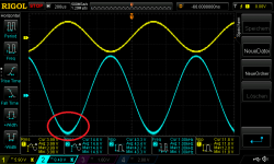
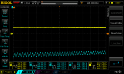
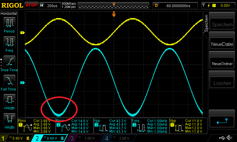
Your 1kHz test... Can you zoom into that area?
That is our main problem with the 1875.
The opamp will try to fix that, but fails.
And filtering that out requires too much sacrification from the THD.
Paralleling the 1875's will help, but we may have better candidates to our setup.
I will test the TDA2050's, FF was kind enough to send me, ASAP so that we see if that has the same phenomenon.
Attachments
Your 1kHz test... Can you zoom into that area?
That is our main problem with the 1875.
....
Hi palstanturhin
here it comes. +/-25V lab supply 8,2R load , 3,5Vrms input
pic 1 inverted amp Gain 3,6 25V supply 8,2Rload_3,5Vrms in 1khz
pic 2 inverted amp Gain 3,6 25V supply 8,2Rload_3,5Vrms in 1khz zoom1
pic 3 inverted amp Gain 3,6 25V supply 8,2Rload_3,5Vrms in 1khz zoom2
this effect comes after watching about 3 seconds. first you see a clean sine wave and then you get this -pic 1
chris
Attachments
Last edited:
Hi again
for going ahead with composite amp i want to ask you which opmap should i use.
4562, 2134 , NE5532 , LM49720, DIL-8
opa1602 , AD8599 - Soic
as i read in some post its needed to use about +/-15V for the opamp to get the best THD (attention some opamps are +/-17V)
which gain should i use?
for building a dual rail for the opamp i am thinking about using a small dual rail converter with about some 100ma current capability- ideas? low noise for sure 😀
some DAC guys using the LT 3045 or TPS74A7xx version for that
during my Class D journey i ordered that:
8 Packung Ultra Klein MP1584EN DC-DC Buck Converter 3A: Amazon.de: Elektronik
chris
Last edited:
Your 1kHz test... Can you zoom into that area?
That is our main problem with the 1875.
The opamp will try to fix that, but fails.
And filtering that out requires too much sacrification from the THD.
Paralleling the 1875's will help, but we may have better candidates to our setup.
I will test the TDA2050's, FF was kind enough to send me, ASAP so that we see if that has the same phenomenon.
Hi
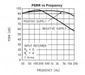
can it be that the "bad" PSRR at the negative Rail is the issue? look at the figure 7 in the datahseet.
chris
Hi
can it be that the "bad" PSRR at the negative Rail is the issue? look at the figure 7 in the datahseet.
chris
Hi Chris,
See below for a similar curve. I will explain.
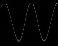
After having drafted my scheme with the different chip-amps (#posting 510) that may be used in a composite amplifier (SE or BTL, dual or double), I got curious about the TDA729X ICs - how close to the supply rail can the output go? I had a very simple mono board PCB so it did not take long to put a TDA7294 in the board and the necessary peripheral components to have a simple inverting TDA7294. Started without load and -27 times gain, and I realized that the output clipping was very asymmetrical (see photo). Checked the DC-levels and all seemed correct so the asymmetrical clipping may be due to a chip defect (the writing on the IC housing was different than the other specimens I have). Before trying to replace the TDA7294, I decided to test stability below the 24dB stated as the minimum gain.
The photo below is taken with +/-30V regulated supply, 1KHz at the input, -3.5 times gain, 1K input resistor, 8 Ohm load and an amplitude in the order of 45Vpp.
You notice the asymmetrical clipping at the top but more importantly the oscillation on the curve below. Just like what you and palstanturhin observed for the genuine LM1875. These oscillations start at a signal level around half the value of that supply rail voltage. The more load current, the worse. Just before clipping it reduces a bit.
A theory: when we go below the minimum gain stated in the datasheet, the risk of such oscillation on the output curve increases. I tried with the square-wave at the input and the overall stability seems fine, almost as with my fake LM1875 in the triple. I could go to -3 times gain and the TDA7294 amplifier would not oscillate or show other instability than the fine oscillations on the negative half. This may be what the datasheet means with a "minimum gain".
The TDA7294 has a higher bandwidth than the LM1875 (at least mine) which is no surprise. In the (oscillating) negative direction, the output would go close to the supply rail.
I will see if I can reduce the oscillation somewhat before changing the TDA7294 IC. I often have problems cleaning plated-through holes for solder.
Attachments
Last edited:
same amp with square wave:
pic 1 inverted amp Gain 3,6 25V supply 8,2Rload_3,5Vrms square in 10khz
pic 2 inverted amp Gain 3,6 25V supply 8,2Rload_3,5Vrms square in 20khz
pic 3 inverted amp Gain 3,6 25V supply 8,2Rload_3,5Vrms square in 30khz
pic 4 inverted amp Gain 3,6 25V supply 8,2Rload_3,5Vrms square in 50khz
pic 5 inverted amp Gain 3,6 25V supply 8,2Rload_3,5Vrms square in 80khz
have a nice day/evening
Hi Chris,
Very nice results. Your genuine LM1875 seem to have a higher bandwidth and slew-rate than my " fakes". I notice some small deviations on the middle of the curve that could be cross-over artifacts. Perhaps my fakes are rather TDA2050 chips inside.
How much feedback capacitance do you have for that test? 100pF?
Since this oscillation is at about 150kHz, and only exists when the amp is sourcing current, could we use a suitably sized output inductor to remove it?
Have any of these tests included an inductor on the output of the amplifier? It seems to me that most serious implementations of chip amps have one, and it might possibly help in this circumstance.
Have any of these tests included an inductor on the output of the amplifier? It seems to me that most serious implementations of chip amps have one, and it might possibly help in this circumstance.
Last edited:
Hi
can it be that the "bad" PSRR at the negative Rail is the issue? look at the figure 7 in the datahseet.
chris
The PSRR is defined as the disturbance from the power-supply rail that will reach the amplifier output (the power supply is the source of the noise). Worst case, you may here have an interaction between the amplifier and a not very low impedance power supply, that is something different. Turbowatch2 pointed to that phenomenon earlier.
I have another theory about the oscillation in my posting #528.
Hi again
for going ahead with composite amp i want to ask you which opmap should i use.
4562, 2134 , NE5532 , LM49720, DIL-8
opa1602 , AD8599 - Soic
as i read in some post its needed to use about +/-15V for the opamp to get the best THD (attention some opamps are +/-17V)
which gain should i use?
for building a dual rail for the opamp i am thinking about using a small dual rail converter with about some 100ma current capability- ideas? low noise for sure 😀
some DAC guys using the LT 3045 or TPS74A7xx version for that
during my Class D journey i ordered that:
8 Packung Ultra Klein MP1584EN DC-DC Buck Converter 3A: Amazon.de: Elektronik
chris
Hi Chris,
Put in an 8-pin socket such that you can try any of the OP-AMPs you mention as you like later. For the component values it will have very little effect (perhaps a little for the square-wave response) when you test it with the oscilloscope and a dummy load. Later with speakers you may hear a slight difference.
I use simple 7815/7915 which is sufficient. Other can be used but will hardly bring an improvement. I hear absolutely no noise in my speakers so save your particular low noise regulators for DACs etc.
Last edited:
Hi Chris,
I have a few comments to issues touched upon by Turbowatch2.
I am happy to see you still have your unparalleled energy for DIY electronics.
When you like to explore a phenomenon, do so because DIY is about learning. Curiosity is the driving force behind DIY.
Sometimes such investigation are of direct relevance for building good amplifiers, sometimes of less relevance.
When we check the square-wave response of an amplifier, it is of course not because we are going to listen to square-wave signals on our speakers but because the speed at which the amplifier output returns to correct level, if forced to deviate by an extreme signal, is important for music signals as well. Can a square-wave at the input be reproduced with almost the same shape at the output, the amplifier very rarely sounds poor. A very relevant test.
We test with moderate capacitance at the output to know how sensitive the amplifier is to speaker cable capacitance. A very relevant test.
We always test the clipping level, less because we want to know the precise power at clipping but because we want to ensure that clipping is regular and not causing strange harmonics or weird oscillation phenomena in excess of what is inherent from a clipped signal. A very relevant test.
We investigate the amplitude range at some two/three different frequencies to make sure that there are no strange non-linear phenomena such as momentary oscillation or visible cross-over distortion and that the amplifier always behave in a predictable manner. A very relevant test.
We do a frequency scan at a moderate amplitude which is realistic for music to know how much bandwidth we have to work with when we make a controlling loop with an OP-AMP. A relevant test.
We could do more elaborate test of the exact clipping level. But whether it is 3% lower or 3% higher, hardly the best ears will notice the difference. It is more that the clipping is regular that matters. So, a less relevant test.
We could do a frequency scan close to the clipping level to see if the protection circuits can be triggered. No music has a signal-level close to clipping for more than a short moment and even if we can make for instance the OCP disturb the regular signal, it leaves us very little useful information. OCPs are for more static use. It is an unrealistic test that leaves pretty unimportant results.
Thus, by asking the question “what will that result tell me about the amplifier?” beforehand, we become more efficient in our testing.
But, there shall always be time for “playing around” as well. And as Turbowatch emphasizes, the important thing in the end is what your ears conclude, not your testing gear though there is a certain correlation.
On the choice of chip-amp, Turbowatch2 with his experience and flawless logic is as such right.
The LM3886 is probably a “winner” as chip-amp, at least on nominal performance. A very high current limit, low THD and good supply voltage range makes it difficult to beat. Further, at a price of 6 Euro from Reichelt in Germany (deutsche Qualität, du weißt) with low shipping costs, the LM3886 is value for money.
So, is there any reason not to go for LM3886 straight away? I will dare a YES. If you want to know about cars, should you buy a Porsche Panamera right away? The moment you assume to have the best why be concerned with something inferior?
LM1875, and TDA2050 for that matter, are solutions for those with a moderately sized room and listening to most classical music, jazz and acoustic music. No need for anything more powerful. Thus, a different “winner” due to particular needs.
Both these two chip-amps and many other also from ST and NXP are both very well playing but in particular suited to give you a broader understanding of amplifier design and the possibility of trimming. My guess is that the 6 months with the LM1875 projects brought you more amplifier understanding than two years with class D because class AB chip-amps let you control far more parameters. For cars, you start with an interesting Seat, then try some VWs and Audi’s, eventually a Mercedes before going for the best, the Porsche. The day you think “I have made enough amplifiers - one last and I stop!” you can make your LM3886 amplifier (and spend your time watching television afterwards).
My humble opinion.
Since this oscillation is at about 150kHz, and only exists when the amp is sourcing current, could we use a suitably sized output inductor to remove it?
Have any of these tests included an inductor on the output of the amplifier? It seems to me that most serious implementations of chip amps have one, and it might possibly help in this circumstance.
I agree that filtering out the oscillation is a possibility.
A good year ago I made an amplifier with TDA2050 that later showed to be fake. They behaved like TDA2030 instead such that with supply voltages above +/-18V, they tended to generate such fine oscillation on top of the ordinary signal. The result was, when testing with +/-23V, that at heavy bass-beats I would hear a kind of "click" in the speakers. For a start I thought it was the current limiter but later when I noticed the oscillation, I believe I heard the "envelope" of the oscillation as I could not hear the oscillation frequency itself. Hence, if the oscillation itself is suppressed but the deformation from the envelope remains, I guess it will still disturb our ears.
First I will try if I can suppress the oscillation.
Hi Chris,
Very nice results. Your genuine LM1875 seem to have a higher bandwidth and slew-rate than my " fakes". I notice some small deviations on the middle of the curve that could be cross-over artifacts. Perhaps my fakes are rather TDA2050 chips inside.
How much feedback capacitance do you have for that test? 100pF?
Hi FF
First i have to excuse my self because I am actually too busy /unconsecrated to follow 100% the audio things. i am sorry. i will stop the science measurements and thank you for your polite feedback - that that is "useless for audio". sometimes i run with energy in the wrong direction.😀
Nice FF that you try the 7294 chip😉.
i use no feedback cap actually...so i missed the 100pF🙄
chris
Since this oscillation is at about 150kHz, and only exists when the amp is sourcing current, could we use a suitably sized output inductor to remove it?
Have any of these tests included an inductor on the output of the amplifier? It seems to me that most serious implementations of chip amps have one, and it might possibly help in this circumstance.
no i use no inductor....so maybe you are right. because i see no inductor at FF´s test i do not use it.
chris
Hi too all
"before you abandon lm1875 , try this."
i do not cancel the LM1875 amp...really not! i "know" from beginning that the LM1875 and its brothers are not the "strongest" chips - that is ok for me. the results are still impressive..
...but i am thinking about other options for the future as i wrote in the other thread (ebay kit mono)
chris
- Home
- Amplifiers
- Chip Amps
- LM1875 in parallel configuration and used in a composite amplifier.