also i wired up another led as someone show to see if there is a power in my circuit. and led is glowing showing that there is power
and im using 1B4148 diode if that makes any difference. i can take any photos but i dont think so that would help cuz its really hard to see connections from photo
and i didint connect pin 4 to negative. but if pin 2 is connected to pin 4 i guess pin 4 is automatically connected to ground
shorted capacitor?(without a meter it's impossible to tell)
inverse polarity on the diode?(ditto)
just because a part looks physically ok doesn't mean it is.
resistors can be open or off tolerance but look ok.
so without a meter how can you be sure the parts you added including the diode are ok (and the right way around)
inverse polarity on the diode?(ditto)
just because a part looks physically ok doesn't mean it is.
resistors can be open or off tolerance but look ok.
so without a meter how can you be sure the parts you added including the diode are ok (and the right way around)
yeah :/ probably i cant 😱
http://www.megaomas.lt/get.image.php?key=image_1&id=4258&thumb=0 this would one work?
http://www.megaomas.lt/get.image.php?key=image_1&id=4258&thumb=0 this would one work?
Spiny
Resistor between pin 7 to pin 8 is 1k
resistor from diode to negative is 100k and other resistor from diode is 1k. capacitor im using is 1uf and capacitor positive connects diode cathode and negative to ground :/ When i connect my audio to pin 5 everything works but only 6 leds blink... when i connect to diode all the leds immiadetly turns off
Its working - Reverse the diode and the leds should blink.
Try some different cap values like 0.5uf (0.47 will be preferred value) or 0.047uf (47nf) once it is working with the diode, a 1n4148 is fine.
To check all are working connect +ve to Pin 5 (or the diode)
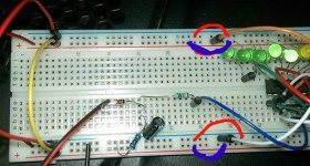
I suspect the reason the last few are not working is a peculiarity of the breadboard. This type has the power lines split in the middle, you need to connect across the gap. See attachment.
Sorry I missed that earlier. With a meter you can check continuity. Handy gadgets, like most folks here I have several mainly cheap ones and one expensive and calibrated one to check the others against.
see this which I think is the type you have.
electronics introduction to breadboards
alan
Attachments
Last edited:
its pretty cheap turk. like 10 euro 😀
tryed reversing the diode and after i touched the my audio wire to diode i could hear cracking sounds😀 i dont think so thats supposed to happen.
Tryed to connect those power lines together but still nothing ;/ Hmmm strange.. i guess if i connect my audio to the diode something should happen no matter 1uf or 0,5uf.. but now nothing happens at all.. not even first led blinking. i might missed some connections but everyyything seems okay without multimeter
i noticed one thing if that would help that if i take out that resistor 100k ohms from diode to negative all leds starts to glow slowly 1 by one. 😀 but after i connect a that resistor as i said.. everything turns off.
You need to connect the power lines, removing the 100K resistor will cause the capacitor to hold its voltage - and the display is showing the voltage climbing.
What are you using for audio? as it is this is suitable for loudspeaker output - and it would be loud! to light all the LEDs
Check the 100K really is should be brown black yellow for the bands on a 4 band resistor (with silver/gold as the finaly band) the image is not good enough to read the bands so can not tell.
alan
haha found out that i mixed two resistors... that one 100K which was supposed to go to negative went to pin 5... Changed now how it should be but still nothing :d yes its 100k. brown black black orange
if you had a meter you'd probably measure that resistor and discover it's 10 ohms (what looks like orange is actually gold (5%)or possibly faded red(2%))100k should be brown, black, yellow the 4th band is tolerance
your shorting your signal to ground
your shorting your signal to ground
i have resistors package of resistors and even on the package it says that this is 100k . its really orange . brown black black orange
ok what color is the tolerance band?(from what your describing this resistor has 5 color bands correct?)
can you show me the pack label (would not be the first time i've heard of mislabeled parts)
can you show me the pack label (would not be the first time i've heard of mislabeled parts)
Last edited:
http://i.imgur.com/qy8nzgt.jpg
yes its abit confusing im not sure from which side should i start counting 😱 if i count from bottom it looks like 100K but if i count from top...
yes its abit confusing im not sure from which side should i start counting 😱 if i count from bottom it looks like 100K but if i count from top...
sry i dont have a decent camera... http://i.imgur.com/J8C6ksX.jpg
here u can see the orange a little bit better
here u can see the orange a little bit better
sry i dont have a decent camera... http://i.imgur.com/J8C6ksX.jpg
here u can see the orange a little bit better
thats 100K its a 5 band one and Brown is 1%
1 0 0 * 1000 (Brown black black Orange) and brown for 1%
the larger gap should be Orange<> brown
the 1K should be Brown black black Brown (brown 1%)
Last edited:
- Status
- Not open for further replies.
- Home
- General Interest
- Everything Else
- lm 3915 vu meter problem.