Hello!Hi Hennady,
Have you measured the impact of the proposed changes?
Of course, I measured and tested with a meander and a frequency generator - with progressive correction, the amplifier is stable and works cleanly ...
subjective perception is also important, and here it is not the placebo that matters, but the quality of the sound reproduction. It is foolish to write off better sound reproduction as placebo.... Or you have based your judgement purely on your subjective impression?
Because Miller's correction is deceiving you. the basis of high-quality sound reproduction is the linearity of the amplitude-frequency characteristic both before the introduction of negative feedback and after the introduction. With progressive correction they make ultra-linear, linear and super-linear top-end amplifiers, with Miller's correction they make do-it-yourself level amplifiers. the non-linearity of the frequency response with such a correction is up to 30dB!!!! - in fact it is a curved amplifier. So who has developed this placebo effect?All components from the kit are just fine. I have made no changes at all. I have measured all significant parameters and have concluded that the amplifier has performed exactly as declared.
Oк.LJM is a qualified and recognized expert
Excuse me, but the topology of this amplifier was developed by Lin, Douglas Self, a similar topology was used by Simpson and Smith, when LJM was probably in elementary school ....who has developed this amplifier and improved it gradually and the amplifier in the present form can be considered as a mature and reliable product.
and Miller's correction was present in all topologies, while the gain was not high, the non-linearity was not so noticeable and it was always possible to make tone correction, Now is the 21st century and high-quality linear signal sources, In this case, progressive correction is used, in fact a combination of differential and integrated circuits, this is necessary for the high linearity of the depth of negative feedback and, as a result, low distortion and high quality sound production. Modern amplifiers almost never do with Miller's correction, because. she is outdated.
P.S.
do you like Miller's correction? It means you're probably having a placebo effect.
I like quality sounding, so in all my amplifiers designed from scratch I always do progressive correction, because I think it's right, that's how we were taught at the university ...
Thank you.Sincerely!
I'll tell you honestly, some time will pass and LJM will make amps with progressive correction only.. There is no other way to improve quality.
Henk
Do you think that's enough to make such bold statements?Of course, I measured and tested with a meander and a frequency generator
There are guys who can "hear" the difference between different brands of capacitors and similar stuff. From my experience and from what I can hear from other experienced guys, that's rubbish.
First, present us some your original work, not just simulations, then judge LJM. He has shown us pretty much competence. Show some respect.I'll tell you honestly, some time will pass and LJM will make amps with progressive correction only.

reading books on which university students are taught is already nonsense for you?Do you think that's enough to make such bold statements?
do capacitors sound better because they have higher quality characteristics, and because they are made using new, more advanced technology?There are guys who can "hear" the difference between different brands of capacitors and similar stuff.
With 1st-order Miller correction in class AB, the amplifier will never sound better than a progressively corrected amplifier, you don’t even need to be a professional listener .... This is the physics of the process ...your sarcasm is unprofessional.
Do you distinguish between Miller correction and progressive correction? or are you a loser?since you speak badly about modeling, then you don’t understand circuitry well, or did you come up with something yourself? why do you need to prove anything? - it's pointless...
What is your problem? I bought a whale - this is my property, I do and redo it as I see fit. What do you have against? Еverything works, characteristics are measured, comparative tests are regularly held ...All you need to know is above in the topic in my post - that's all ...First, present us some your original work, not just simulations,
Last edited:
I would like to warn these who want to build amplifiers based on available LJM kits to refrain from making modifications before verifying their real efficiency. Kits are of good quality, the design is technically sound. The declared THD values are real, other significant parameters too. The most of these suggested "improvements" just degrade the performance and increase the risk of the failure of the amplifier.
The same happened to me: even before receiving the kit I have made a list of modifications and purchased "components from trustworthy supplier". Now, looking back with much more knowledge and measuring equipment I have realized how foolish these "ingenious" modifications were.
Now I have decided to remove all these modifications and re-build all LJM projects from the components contained in the kits. I have verified transistors from the MX50SE kit with the use of curve tracer. All of them are good. These LJM kits have indeed great value taking into account their low cost.
Do not change anything!
Last edited:
You are absolutely right, radio amateurs must be warned against wiring errors in the ground wiring in the amplifier, because. simple boards MX50SE has a high parasitic inductance of the installation, which is why it is necessary to shunt all electrolytic capacitances in the power supply on the board with film capacitors. I think it will not be difficult for LJM to confirm his competence and install such shunt capacitors immediately when developing a printed circuit board, he himself said that these capacitors cost a penny, then why not?I would like to warn these who want to build amplifiers based on available LJM kits to refrain from making modifications before verifying their real efficiency.
To modify the finished board, you need the appropriate skill and knowledge, if there is any doubt about this, then it’s better to really not touch anything and listen to the amplifier as it is - inexpensive sound for little money ...
yes, but the problem of this amplifier is the Shiklai output stage, the level of distortion of which does not make it possible to adequately evaluate the contribution of progressive correction to the measured parameters, but subjectively, the sound certainly improves and becomes cleaner because the input differential stage is not overloaded on a high-frequency signal signal.The declared THD values are real, other significant parameters too.
Miller's correction cannot provide the necessary depth of negative feedback on high frequency and subtract this high level signal at these input frequencies. Because of this, there is an overload on the high-frequency at the input and the effect of "transistor sound" ...
Quoted for truth.I would like to warn these who want to build amplifiers based on available LJM kits to refrain from making modifications before verifying their real efficiency. Kits are of good quality, the design is technically sound. The declared THD values are real, other significant parameters too. The most of these suggested "improvements" just degrade the performance and increase the risk of the failure of the amplifier.
The same happened to me: even before receiving the kit I have made a list of modifications and purchased "components from trustworthy supplier". Now, looking back with much more knowledge and measuring equipment I have realized how foolish these "ingenious" modifications were.
Now I have decided to remove all these modifications and re-build all LJM projects from the components contained in the kits. I have verified transistors from the MX50SE kit with the use of curve tracer. All of them are good. These LJM kits have indeed great value taking into account their low cost.
Do not change anything!
I have also made that experience.
Experience is really made up of failure. In order for an attempt to consist of successful solutions, knowledge is needed.I have also made that experience.
The correction option that I implemented in my own completely utilizes the desire to listen after that with Miller's correction. But I do not insist, and it is better not to really try to change something if all your knowledge is just a bad experience.
The truth is that there is always the possibility of comparing the sound before and after....
Miller's correction breaks the frequency response of the amplifier right in the audio frequency range ...Don't repair what isn't broken.
to speak on the curve, that it is direct, is that correct?
Why do you persist without the proof that this modification works?Miller's correction breaks the frequency response of the amplifier right in the audio frequency range ...
to speak on the curve, that it is direct, is that correct?
The right method is:
1. Definitoon of the problem
2. Analysis of the problem
3. Hypothesis
4. Test with experiment
5. Data analysis
6. Report conclusions
But your method is very special:
1. Hypothesis: Hennady Kowalsky is 21th Century Eddison
2. Adjust the conclusions without testing to support the Eddison Hypothesis
3. Throw a pile of Audiofoolish stock phrases
4. People apply yet another Snake Oil to otherwise good product.
We would like to trust you but based on published and repeatable results.
I am sory, but I don't think that just your gutt feeling is enough to take your claims seriously.
And don't throw toys from your pram again.
I had not read the messages preceding the post by Berlusconi which I was replying to. My comment was not meant to be in context with your posts.Experience is really made up of failure. In order for an attempt to consist of successful solutions, knowledge is needed.
The correction option that I implemented in my own completely utilizes the desire to listen after that with Miller's correction. But I do not insist, and it is better not to really try to change something if all your knowledge is just a bad experience.
The truth is that there is always the possibility of comparing the sound before and after....
Now that I have read the preceding discussion, I must say that your build looks very good.
About Miller compensation I hear it's good enough, though there are more advanced schemes. It is known.
This modification works right now, just like the ones I've been collecting for the last 30 years.Why do you persist without the proof that this modification works?
You do not have the relevant knowledge to prove something to you.
thanks, use them for yourself, it's not interesting to communicate with you.The right method is:
Thank you, I didn’t photograph and fix all the works, but now I have free time for this.Now that I have read the preceding discussion, I must say that your build looks very good.
Miller's correction of the 1st order works up to the cutoff frequency of the transistor, which is about 30 MHz, then this frequency-dependent NFB turns into Positive Feedback, because. there is no gain and the current grows, the amplifier does not whistle because the input stage operates at a lower frequency; the input capacitance is responsible for this, which is placed at the input of the amplifier after the input resistor, i.e. together they limit the gain of the circuit starting from the frequency of 2kHz MX50SE (market), the non-linearity to the coverage of the NFB is almost 15dB - this is not good .... these 15dB less depth of negative feedback, which should additionally reduce the input signal by 5.6 times at a frequency of 20 kHz, but this does not happen. Progressive equalization is a combination of diff and integrated RC circuits, the goal of which is gain linearity over the entire audio frequency band. There are also Miller variants of the 2nd and even 3rd order, but they require a more careful selection of active elements in terms of parameters and are rarely used on transistors in home-made versions.About Miller compensation I hear it's good enough, though there are more advanced schemes. It is known.
I posted a variant with progressive correction where integrated circuits to ground are used. This option is the simplest and it turned out to be the most musical by ear. There was a variant of progressive correction with compensation for the in-phase operation of the diff cascade in the circuit, but Shiklai's assembly, which is disgusting for audio with a long tail of distortion at high frequencies, does not make it possible to fully implement such a solution. Therefore, I settled on a simple option.
And yes, on the board it is necessary to shunt all electrolytic capacitors with film capacitors of 0.1 - 0.2 microfarads each - this is actually mandatory, only they are not initially on the board - this is bad.
It is also mandatory to use the protection of the speaker system, because. there are no protections in the circuit.
Last edited:
Thank you for the good explanation of Miller correction, you filled in the blanks for me.Thank you, I didn’t photograph and fix all the works, but now I have free time for this.
Miller's correction of the 1st order works up to the cutoff frequency of the transistor, which is about 30 MHz, then this frequency-dependent NFB turns into Positive Feedback, because. there is no gain and the current grows, the amplifier does not whistle because the input stage operates at a lower frequency; the input capacitance is responsible for this, which is placed at the input of the amplifier after the input resistor, i.e. together they limit the gain of the circuit starting from the frequency of 2kHz MX50SE (market), the non-linearity to the coverage of the NFB is almost 15dB - this is not good .... these 15dB less depth of negative feedback, which should additionally reduce the input signal by 5.6 times at a frequency of 20 kHz, but this does not happen. Progressive equalization is a combination of diff and integrated RC circuits, the goal of which is gain linearity over the entire audio frequency band. There are also Miller variants of the 2nd and even 3rd order, but they require a more careful selection of active elements in terms of parameters and are rarely used on transistors in home-made versions.
I posted a variant with progressive correction where integrated circuits to ground are used. This option is the simplest and it turned out to be the most musical by ear. There was a variant of progressive correction with compensation for the in-phase operation of the diff cascade in the circuit, but Shiklai's assembly, which is disgusting for audio with a long tail of distortion at high frequencies, does not make it possible to fully implement such a solution. Therefore, I settled on a simple option.
And yes, on the board it is necessary to shunt all electrolytic capacitors with film capacitors of 0.1 - 0.2 microfarads each - this is actually mandatory, only they are not initially on the board - this is bad.
It is also mandatory to use the protection of the speaker system, because. there are no protections in the circuit.
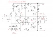
I will present a version of the modification, which is also practically implemented and delivers a lot of positive emotions with its sound. The principle of modification is to correct with an active filter at the input of the circuit, for this an input differential stage is used which has a gain of 30dB, which allows the use of very small capacitances (47pF) while the depth of Negative feedback remains linear (+/-1.5dB) during throughout the audio frequency band from 20Hz to 20kHz.
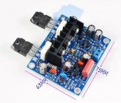
In the attachment there is a market version of the MX50CE which is already soldered on the board.
Circled in red elements that have been changed or reconnected to improve performance.
In the stock version, when powered by +/-36 volts, the initial current of the output transistors was only 45 mA.
Shiklai's output cockpit with such an initial current of the output pair operates with a distortion of 6.4% at a frequency of 20 kHz at a nominal input voltage, and only thanks to negative feedback this value decreases tenfold, but this is still not enough for high-quality sound reproduction.
continued in next post....
Attachments
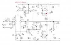
What was done (see attachment):
C1 replaced with a 10mF metal film capacitor
R2 increased to 2 kOhm
C2 is reconnected between the base and collector VT5 its capacitance is reduced to 47pF
R13 increased to 680 ohms. - this is done so that the sensitivity at the input becomes 1.5 volts (RMS)
R15 is shunted with an additional ceramic capacitor C15 with a capacity of 47pF
C7 is reduced to 22pF and reconnected from the collector of transistor VT9 to ground.
C9 in the market version was used electrolytic, which is categorically unacceptable, so it would be replaced with a VIMA film capacitor with a capacity of 0.22 microfarads.
A trimmer R32 is added in parallel with the R20 resistor, with its help the output assembly current is adjusted at the level of 185mA - with this output stage distortion value less than 1% (20kHz) at the rated input voltage. The total negative connection minimizes these distortions to the level of 0.048% (20kHz). Setting the initial value of the output stage current is carried out with a voltmeter according to the required voltage between the collectors of power transistors, the voltage should be 37mV.
adding trimmers R33 or P34 allows you to minimize the DC voltage at the output of the amplifier, which can be more than 3mV due to the spread of the parameters of the circuit elements.
L1 R35 was added to eliminate the influence of the capacitive nature of the speaker load on the transient response of the amplifier. With this circuit, there is practically no influence.
P.S. After such a modification, the input active filter P2 / C2 / BT5 is responsible for the correction and is 89 kHz, while the gain of the Open loop at a frequency of 1 kHz is 83 dB, and at 20 kHz it is 81.8 dB !!!
Unity gain frequency 3.7MHz,
Transient response without outliers.
Everything is stable - the amplifier works quietly without extraneous noise, very clean highs, good sound stage, wide stereo panorama, and there is no bland sound called the "transistor sound" effect, which is typical of Shiklai output stages.
Attachments
Last edited:
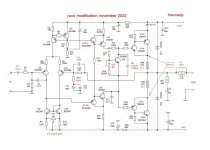
When asked about my opinion on finalizing the circuit, I see it in the following form (see attachment).
The basis for refinement is to replace the single transistors of VAC cascade with assemblies of two low-power transistors VT14 / VT15 - this will improve the frequency properties VAS and increase the input impedance for the amplifier on the input transistor VT5. As a result, the gain of the input stage will increase by 27 dB, and the gain of the open loop at a frequency of 1 kHz will be 116 dB, and at a frequency of 20 kHz 94 dB, the increase in non-linearity does not matter, because. the depth of the total negative coupling at a frequency of 20 kHz significantly exceeds 60 dB, and at a frequency of 1 kHz it is 92 dB, i.e. in fact, an ultra-linear amplifier is obtained from such a simple circuit.
Next, resistance R14 (62R) is added, it is necessary to reduce the overcompensation level of the dependence of the initial current of the output transistors on temperature, i.e. the thermal stability of the circuit parameters is improved. This resistance improves R14 thermal stability by more than 2 times.
The remaining changes are not significant and relate more to setting the circuit parameters during manual assembly by a radio amateur.
A supply voltage of more than +/-36 volts is not desirable.
The max output power with this supply is 125 watts into 4 ohms - this is essentially the limit for the output transistors used.
With a rated output power of 45 watts into a load of 4 ohms, distortion at a frequency of 1 kHz does not exceed 0.0015%.
In fact, this is HiFi quality, which will be enough for home audio ...
Attachments
I agree with you about evrything regarding Miller correction!Simply destroys the music...
- Home
- Amplifiers
- Solid State
- LJM MX50 kit amp