Did not try that one...
Just changed the Rl into 2 Ohms and the frequency to 20Khz 😀
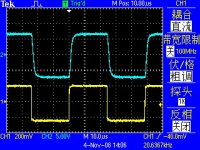
Came out like this...😕
Ignore the circuit picture.
It is my free graffiti. Not really circuit diagram.
The actual measurement.
Attachments
Hi guys i've built this amp and it is great!!!
I want to ask can i use a pair of 1943 5200 instead, and if yes am i going to get more watt from this amp?
My tranformer is 2*34v ac.
It can use many transistors. Including A1943 C5200
Of course. Can also be this. Smile.
Attachments
LJM. Can you find those Sankens and offer them forsale? Also Your MX 50x2What color are your circuit aboards? Driving a 4 ohm load would be ideal...... Glad to see you check in once in a while......
a
a
a
a
Hi LJM,I design the amplifier. Named MX50.
The reason is I put it in the design of 50 w eight r amplifier.
So it's circuit for more than 50 v dc.
Nice to meet the designer here.
Little question about the MX50 : 50V dc . Do you mean +/- 25V or +/- 50V ? Makes a lot of difference 😉
LJM,
Glad to see the designer here. I believe that is a big step forward from cheap copy to products designed by an engineer who will stand behind it and answer questions. I believe it is time for Chinese companies to quit using the coat tails of others and stand up: "This is my design and it is good".
I hope you have gotten some good feedback. I worked through it for 12V rails and 22V rails and found a few small resistor changes to be quite beneficial in simulation. We all should know, simulation is not the same as reality! We also have the problem of incorrect SPICE models for the transistors you supply. I used ones that were a close guess. When I build it, the compensation may have to change. I even modeled it as a 6W class A amp.
I would love to see you do a vendors forum where you could collect and pass on ideas. Recommend an output network. Recommend a DC protection and mute circuit ( For all I know you sell one) Suggest heat sink specifications for different power supply voltages. You could get quite a following I expect as a great first timer project.
Crispy,
Driving a 4 ohm load is a BAD idea for any amp. Don't expect an amp with only one output pair to do that well. Where I expect an amp to be stable at 2 or 3 Ohms, I expect my load to be above 6 in use. It is just physics. 8 Ohms is more of a standard for specifications as I don't think I have ever actually seen a 8 Ohm speaker. You also mention alternative transistors. That is expensive, so respect LJM is making a good little CHEAP board we can play with.
Model it is SPICE. Do the SOA calculations. Do the heat sink calculations.
I would caution others. With higher voltage rails, it will do as advertised, but with no I/V limiting, if you play it too loud into a low impedance load, you could burn it up pretty quick. This is a SMALL amplifier. It should suit most rational users fine as long as you don't abuse it. 4 Ohms is abuse.
johndaf
Larger outputs mean it will not fry as quickly and you can push it harder. How much power you get out is a matter of the voltage supplied and the load across it. Not the transistor. The transistor defines how much power you can SAFELY get out.
Larger outputs mean it will not fry as quickly and you can push it harder. How much power you get out is a matter of the voltage supplied and the load across it. Not the transistor. The transistor defines how much power you can SAFELY get out.
LJM. Can you find those Sankens and offer them forsale? Also Your MX 50x2What color are your circuit aboards? Driving a 4 ohm load would be ideal...... Glad to see you check in once in a while......
a
I'm glad to discuss with you.
MX50SE MX50X2 and they are not the same circuit structure.
I can purchase all kinds of transistor. Of course, their prices vary widely.
I choose, performance and sound close to, but to sell the lower model.
Their prices vary widely, but using the difference is not imagination in so big.
Hi LJM,
Nice to meet the designer here.
Little question about the MX50 : 50V dc . Do you mean +/- 25V or +/- 50V ? Makes a lot of difference 😉
Because many 50V100UF MX50SE use of electrolytic capacitors.
So they can not use more than 50V voltage.
And a higher voltage, the transistor will operate in the larger power. This deviates from the design planning.
LJM,
Glad to see the designer here. I believe that is a big step forward from cheap copy to products designed by an engineer who will stand behind it and answer questions. I believe it is time for Chinese companies to quit using the coat tails of others and stand up: "This is my design and it is good".
I hope you have gotten some good feedback. I worked through it for 12V rails and 22V rails and found a few small resistor changes to be quite beneficial in simulation. We all should know, simulation is not the same as reality! We also have the problem of incorrect SPICE models for the transistors you supply. I used ones that were a close guess. When I build it, the compensation may have to change. I even modeled it as a 6W class A amp.
I would love to see you do a vendors forum where you could collect and pass on ideas. Recommend an output network. Recommend a DC protection and mute circuit ( For all I know you sell one) Suggest heat sink specifications for different power supply voltages. You could get quite a following I expect as a great first timer project.
Crispy,
Driving a 4 ohm load is a BAD idea for any amp. Don't expect an amp with only one output pair to do that well. Where I expect an amp to be stable at 2 or 3 Ohms, I expect my load to be above 6 in use. It is just physics. 8 Ohms is more of a standard for specifications as I don't think I have ever actually seen a 8 Ohm speaker. You also mention alternative transistors. That is expensive, so respect LJM is making a good little CHEAP board we can play with.
Model it is SPICE. Do the SOA calculations. Do the heat sink calculations.
I would caution others. With higher voltage rails, it will do as advertised, but with no I/V limiting, if you play it too loud into a low impedance load, you could burn it up pretty quick. This is a SMALL amplifier. It should suit most rational users fine as long as you don't abuse it. 4 Ohms is abuse.
From my test results.
MX50SE work + - 30V DC 4 ohm impedance is not a problem.
At maximum conditions, it outputs a voltage of about +-28V, 4 ohm load. You can get about 100 watts power.
MX50SE recommend not more than 100 watts output power.
So that we can calculate.
It is the next 8 ohm load, it is recommended voltage +-40V.
4 ohms, recommended voltage +-28V
2 ohms, recommended voltage + - 20V
Transformers suggested more than 250VA, stereo.
Under transformer power remains unchanged, the lower the voltage, current increases.
Reduce the voltage, increase the current, is a method to cope with low-impedance load.
Of course, the power output is always close to it. If you need a low-impedance greater power, you need to select the parallel transistors. Or more power transistors. They are always more expensive or larger volume.
johndaf
Larger outputs mean it will not fry as quickly and you can push it harder. How much power you get out is a matter of the voltage supplied and the load across it. Not the transistor. The transistor defines how much power you can SAFELY get out.
Ok thanks!
Hi LJM
Will this amplifier be able to drive 2.7ohms speakers for a long period of time? And if i supply it with +-2 VDC what will the watt rating be?
Will this amplifier be able to drive 2.7ohms speakers for a long period of time? And if i supply it with +-2 VDC what will the watt rating be?
Use 8 Ohm speakers. 2.7 ohm speakers will definitely lead to problems or bad sound.Hi LJM
Will this amplifier be able to drive 2.7ohms speakers for a long period of time? And if i supply it with +-2 VDC what will the watt rating be?
If you want to apply 2.7 ohm speakers, buy a Mark Levinson amp.
The reason the speakers are 2.7 ohms, is beacuse its Car audio speakers, was thinking of using these boards for my Car audio amplifier project! 😀
I do not think that the MX-50 is suited for a car audio project. Low impedance speakers would require at least 3 output pairs (and current limiter in the output stage). Besides, a class AB amp produces too much heat to be applicable in a rather hostile environment like a car ( temperatures of over 50 Celsius are common in full sunshine).The reason the speakers are 2.7 ohms, is because its Car audio speakers, was thinking of using these boards for my Car audio amplifier project! 😀
Charlie - I hear what you are saying. At this point in my life, I have little time to learn the infinite details of amp design. But that's a personal choice. My forte is building the complete amp - hopefully including a rock solid designed amp module. I would much rather start with a proven PCB design with quality parts, without having to do a lot of component shuffling to wring that last % of THD from the amp than start from scratch. I don't fault others that do though either. 🙂You should get the MX50X2 then, that adds two more output transistors per side but it's not that dirt cheap.
My opinion however is the first watt counts. I think I hardly go over a few watts or let's be generous and say 10W with normal in room listening. That means 95% of the time casual listening volume that you might need to talk with your voice raised somewhat, and the rest 5% when I go louder for a track or so. And I believe this is what most people do whoever lives in a flat with neighbours around.
I doubt if 4 amps per side is not enough for that. I easily popped a 4amp fuse with a volume knob setting that I never even once tried to reach with normal listening. It was the fuse, and not the output.
And at the end what really matters is how it sounds, and I tell you, it sounds damn good, being cheap is a nice extra.
Problem I'm finding with that approach is no matter what kit you buy, based on reputation read on the hundreds of DIY threads, there is always someone claiming the design could be better. Can't anyone design the 'perfect' amplifier encompassing all the proven techniques that provide a 'better than good enough' sounding amp without having to adopt the musical chairs approach with components?
Why are there thoses that will praise a class D amp sound, while others will loathe it saying, I've never heard a class D amp I like! It seems like when buying an module from Asia, that it's like playing amplifier roulette! Regardless of the one you choose it's never the right choice or it will have some flaw(s). Hopefully not dangerous flaws! So, we could spend countless hours weeding through the pages and forums here and never discern the best amp. That's because there isn't one. Maybe it won't be the best amp, but there has to be some designs that are 'better than good enough' for those of who enjoy music at a level just shy of the audiophool crowd.
I've expressed here on more than 1 occasion that I'm a big fan of class D amps and have built a few varieties and for the most part can't tell one wit of difference between them! Maybe that's because they do all sound very similar, or my 61 yr old ears are loosing their golden touch they had in my youth. 🙂 Having said that though, my next project is the infamous Honey Badger amp! Whoa.
redjr
The reason the speakers are 2.7 ohms, is beacuse its Car audio speakers, was thinking of using these boards for my Car audio amplifier project! 😀
Very bad choice. This amp is not designed to be a car amp. Different problems, different solutions. Get a car amp.
Adding more pairs to a CFP output is likely to get you into stability trouble. That is why almost all high current amps are EF outputs.
A "perfect" amp? LOL! Amplifier design is a matter of engineering choices. There is no perfect amp and never will be. The MX50 is a solid design for what it is intended to be. Not sure I would call the parts supplied as premium choices, as it is very cheap. Could one do better? Of course, I have beat this thing to death and made different choices than the designer within the same basic design. Better? for me, yes. For you? It depends. If you want a nice little amp in the 40 to 50W range for well behaved ( 6 Ohm) speakers and understand enough about power and ground layout, why you must add an output network, why you should add a DC protection/turn on mute circuit, then this is a great basic way to start. It may be hard to believe, but this is actually engineering. People go get PHD's in this stuff. ( several hang around right here)
A "perfect" amp? LOL! Amplifier design is a matter of engineering choices. There is no perfect amp and never will be. The MX50 is a solid design for what it is intended to be. Not sure I would call the parts supplied as premium choices, as it is very cheap. Could one do better? Of course, I have beat this thing to death and made different choices than the designer within the same basic design. Better? for me, yes. For you? It depends. If you want a nice little amp in the 40 to 50W range for well behaved ( 6 Ohm) speakers and understand enough about power and ground layout, why you must add an output network, why you should add a DC protection/turn on mute circuit, then this is a great basic way to start. It may be hard to believe, but this is actually engineering. People go get PHD's in this stuff. ( several hang around right here)
Hi LJM
Will this amplifier be able to drive 2.7ohms speakers for a long period of time? And if i supply it with +-2 VDC what will the watt rating be?
Seriouslly? 2V?
- Home
- Amplifiers
- Solid State
- LJM MX50 kit amp