"That would explain why the amps you mention were not very pleasing amps to listen to. "
Confirmation bias?
McIntosh makes three amplifiers that have the exact same driver card, and either one, two, or three pair of outputs. The one with two pair of outputs sounds the best.
I doubt you ever heard an Ampzilla III, it failed as a commercial venture, and none were ever produced (unless you saw the schematic and built one from scratch).
So what do you think of the Bryston two pair output stage, one pair common collector, the other pair common emitter? Have you heard one?
I heard an Ampizalla as built form PE. Type one? I have never like any of the Mac's. Built like tanks. Last forever. Quality no question. I just think they are rather bland and lacking detail. Even their "great" tuners, I found several others I prefer. Sansui, Kenwood, Nalamichi. A well designed card IPS/VAS should be usable across a range, especially if it is a three stage output. Smart engineering. Mac is not in the market to make their small amp a cost cutter budget unit, so they have no need to take a few parts out. I respect them, I just don;t like them.
I have not heard the Bryston. I keep trying to get my hands on one. Some absolutely love them, some not impressed. Again, top notch quality. I thought I was going to get my hands on a 4B for a weekend, but it fell through.
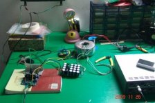
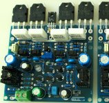
Greeting, I received my MX50-se kit today and stuffed the cards. I now need to mount it to my heatsink. I'm using an old Radio Shack receiver for a chassis & pwr supply. +-43VDC. What size tap do I need for mounting screws for outputs. I have the old mounting screws, that are metric fine thread. The mounting hole looks to be 3mm. My taps on hand are too big. Hopefully I can buy one tomorrow & keep progressing. OK, I'll be updating as it happens.
OK, I got 3.50mm tap & it matches the original screws=perfect. It says use drill #40. I'm back in business.
Having more fun with SPICE lies. If I reduce the IPS degen, distortion goes down. Too much. Leaving them at 22.1 Ohms.
Thermal simulation suggests it is way over compensated. Only bench testing will tell.
Changed a bunch more values. My 12V version sims at about .004% Strange, looking at bias and distortion. A low spot at about 13 mA, climbing below that. A hump at about 100 mA. Then going down as current goes up and you progress into full class A. I think I have enough heat sink to run about 135 mA.
Baker clamp does a very nice job on the lower rail, but with the low power version I am doing, I have noting to keep it off the top rail.
Doing a 12 V, 6W version so on the bench I can stress it to see how it behaves with a real speaker load at clipping and with thermal changes. The plan right now is one dead stock, one fully tweaked. The junk box is not as fully populated as I thought, so I have to order a few parts. Full tweak will have separate bridge and caps for the IPS/VAS.
I actually have a big enough transformer and heat sink, I could bias it up to class A. 🙂
Interesting, tvrgeek... I'm about to order one myself.
My idea is to use a 18V*2 transformer (120 VA) giving some over 24V dc. Power 25 to 30 watts into 8 Ohms.
Question: in the original schematic the bias current is fixed. Which resistor ought to be replaced by a variable resistor to control the bias current?
My idea is to use a 18V*2 transformer (120 VA) giving some over 24V dc. Power 25 to 30 watts into 8 Ohms.
Question: in the original schematic the bias current is fixed. Which resistor ought to be replaced by a variable resistor to control the bias current?
Interesting, tvrgeek... I'm about to order one myself.
My idea is to use a 18V*2 transformer (120 VA) giving some over 24V dc. Power 25 to 30 watts into 8 Ohms.
Question: in the original schematic the bias current is fixed. Which resistor ought to be replaced by a variable resistor to control the bias current?
The one on on the bottom half of the bias transistor pair that sets bias.
I have so many MX-50 schematics,none matching the boards so I can't give a number. Here is my highly modified version. Lots of small changes. I don't recommend doing these changes unless yo are ready to bench test as simulations and reality are different. In my schematic, it is R16.
My version changed to Transient Miler Compensation, Moved the IPS shunt to be a bootstrap, changed currents everywhere etc. I am doing such low power to be able to reach clipping easily for testing and A/B listening one stock, one my modifications. This version is NOT a recommendation for others to build, it is for test.
For a complete amplifier, I hope you are also getting something like ESP's speaker relay kit. Loudspeaker Protection and Muting
Chassis layout is critical and that does not show up in a schematic.
When I finish testing, I am going to rebuild them for my 22V chassis.
Attachments
Tvrgeek, thank you for your answer! 😉
And, yes, a degree of dc-activated loudspeaker cut-off is part of the plan.
The location for the variable resistor is now clear to me. I was not sure if the upper- or lower resistor ought to be replaced.
As you advice, I will not build the 12V version. It was not the plan, nor fitted the requirements (25W in 8Ohms).
Cheers,
Edwin
LOWER!!!!! That way if it fails, as POTS are unreliable, you kill the bias. If you do the upper resistor and it opens up, you run the bias up and fry. Connect the pot so the element is end to end and the wiper tied to one end. That way it will never be higher value than the pot.
Don't worry, that's what I understood 😉LOWER!!!!! That way if it fails, as POTS are unreliable, you kill the bias. If you do the upper resistor and it opens up, you run the bias up and fry. Connect the pot so the element is end to end and the wiper tied to one end. That way it will never be higher value than the pot.
Here are my SPICE models. Please note I could not find models for all the parts as supplied, so I made fair guesses to some. Not all the parts I used are in the LTSpice library, so you have to hunt them down as I did. Some don;t matter, like using the 1N4001 on the output instead of a 4007. The outputs I modeled are quite good and probably have higher gain.
I am going to use the original parts with the exceptions of the resistors I changed, power supply mods, and additional caps for the compensation. I have everything in my parts box. I hope I have enough stuff to make a DC sense and power up/down circuit. I don't intent to spend any cash on this. Saving that for my Reasonable.
Playing around with some values I got THD down to .0052% @ 20Khz in 8 Ohms (24 Vdc)
Changes in the MX-50-Improved schematic:
Vdc + and - 24Vdc (was 32 V dc)
R10,R11 75 Ohm (was 68 Ohm)
R6 1200 Ohm (was 1K Ohm)
C16 .68uF (was 1uF)
R17 2.1Kohm (was 2Kohm)
C6,C11 68pF (was 100pF)
R12 80 Ohm (was 100 Ohm)
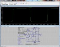
Be sure it is still stable. With a 4 Ohm load, be sure you don't get any issues at hard clipping. Then put in a square wave ( half a volt will do) to be sure you are OK. Unless you are driving an 8 Ohm resistive load, you could be in for a big unhappy surprise. I go for 2 Ohm resistive load as a fair margin considering an 8 Ohm speaker is about 6 and it is a complex impedance. I have been trying to work up a realistic "bad" load.
Reducing the compensation does really make a difference, but you may find you have to jack it back up for stability.
If you can get the Tian probe technique to work, better test. I also look at the AC zero gain point and then put in a AC at that freq ( about 12 meg) and look for peaking in the AC test.
To get the square wave to work, you have to bypass the input cap and short the LF feedback cap
All this teasing is my attempt to learn about it. I can only say what I have found and not as an "expert". If I build a 100 or so designs over 20 years after getting my PHD, then I could climb under the wing of some of the true experts who haunt out forums.
My 6W version is going to be built into my speaker test gig. I have plenty of good amps already.
Did not test for stability yet. I certainly will. Actually it was one of the questions I asked myself reducing the values of some capacitors. It sure made the amp faster, but what about stability and oscillation issues? 🙁Be sure it is still stable. With a 4 Ohm load, be sure you don't get any issues at hard clipping. Then put in a square wave ( half a volt will do) to be sure you are OK. Unless you are driving an 8 Ohm resistive load, you could be in for a big unhappy surprise. I go for 2 Ohm resistive load as a fair margin considering an 8 Ohm speaker is about 6 and it is a complex impedance. I have been trying to work up a realistic "bad" load.
Reducing the compensation does really make a difference, but you may find you have to jack it back up for stability.
If you can get the Tian probe technique to work, better test. I also look at the AC zero gain point and then put in a AC at that freq ( about 12 meg) and look for peaking in the AC test.
To get the square wave to work, you have to bypass the input cap and short the LF feedback cap
All this teasing is my attempt to learn about it. I can only say what I have found and not as an "expert". If I build a 100 or so designs over 20 years after getting my PHD, then I could climb under the wing of some of the true experts who haunt out forums.
My 6W version is going to be built into my speaker test gig. I have plenty of good amps already.
I, however , am quite sure of the modifications on the input differential stage. The little tweaking on the current-source made some difference in the THD figures, as well as the emitter-resistors of the lower transistor pair.
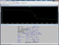
I did check on clipping. I did not mention raising R6 to 720 Ohms. Output 20Vpeak and no clipping.
The 68pF's, with the Q7 emitter resistor, appear to be an optimum value (under these conditions). Distortion drops some further ten- thousands of a percent.
As far as I'm concerned about .005% (at, about, full power and 20Khz into 8 Ohms) is about the maximum this design yields. Quite nice.. 😉
So why tweak distortion at 20 Khz and not 1 Khz? Our audible spectrum ends at 20 Khz, not at 1Khz. When THD is optimal at 20Khz, I expect the amp to be fast enough so THD at 1Khz won't be higher.
Last edited:
Just tried this one:
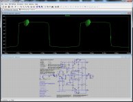
Load : (3 Ohms in series with 4mH) // 2uF (= shitty loudspeaker 😎)
Input : 1000Hz @ +20db clipped with 2 diodes
Result : a nice "squarewave" with perfectly rounded top/bottom and an approx. -.8V offset but further no unwanted symptoms...
Load : (3 Ohms in series with 4mH) // 2uF (= shitty loudspeaker 😎)
Input : 1000Hz @ +20db clipped with 2 diodes
Result : a nice "squarewave" with perfectly rounded top/bottom and an approx. -.8V offset
but further no unwanted symptoms...Attachments
Last edited:
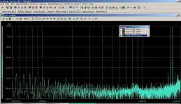
We look at 20K as that shows us how fast the knee is rising. In my speaker building experience, I am also concerned with the first couple of harmonics that land above 20K as they excite tweeter breakup. 20K right below clipping is a worst case calculation.
The goal is not so much the number, as anything below .01 is probably more than good enough, but how it behaves. How it approaches clipping. How it recovers. Is it consistent? These are the secret sauce the experienced folks know we don't learn just from simulation. Number chasing gives us the lifeless "transistor" sound of the 80's Japanese receivers when numbers were for bragging rights. Look at the FFT and see how the higher harmonics fall away. Do they steadily decrease, stay about the same, or actually rise? Lower the freq of the test signal and see what lands in the 2 to 5K range when yo hit it with clipping in the bass. Here is where you are not looking at absolutes, but comparison between simulations with identical FFT parameters.
Chasing the number, for a given topology is useful. Look at all the currents right below clipping into a low load. Be sure you are not starving something, like the driver base. Go back and do the noise simulation after changing currents to be sure you did not trade one problem for another.
We can't really compare numbers, as small changes to the FFT parameters have as big an effect as the circuit. I have values that seem to tell me consistent things. They are different from some of the widely published ones. I have just started to look at what happens with stable DC conditions and then a single pulse. I have not done any two-tone simulations.
I have been deep into this for only the winter, so I have learned SO much, I know I know almost nothing. Keeps me out of trouble and kept me busy enough not to buy some ribbon tweeters I want to get my hands on. Spice is cheap!
My 22V version calculates as .0068%, but is stable into 3 Ohms clipping. I think I can do better. I got .005 in the 12V version ( the one I am actually going to build) Again, stable 3 Ohms hard clipping. At 1K and a more rational input, less than half that. I am looking at the tradeoff on the amount of compensation vs the topology. TMC looks fantastic at first, but in some cases, conventional may allow much lower values for worst case loads and be a better choice.
If you increase the lower rail bypass cap from 100u to 470u, it reduced the noise injected into the VAS by a ton. The top rail does fine with 100u. Add some series resistance to the power source ( .1 or so) and you will see more realistic rail ripple. Actually modeling a real supply is even more informative.
Big payoff: Taking what I learned in amplifiers, I just re-did the crossover for my budget SilferFluke/Dayton build getting rid of a bad midrange impedance hump and now getting a beguine rising inductive load. I was in the midst of building a "ugly load". The real lesson is of course to start off with much better drivers, but this was a demonstration on why.
Bingo. Worse case is a real pain if number chasing. If you have great confidence in the load it will see, you can back off some. It all depends on the load.
Here is what I am building as my test amp for speaker evaluation. It will also have my MOSFET rail protection system I am working on as the probability of shorting the outputs on the test bench is very high! I took out some tricks as they are not appropriate for the use ( separate rectifiers and caps for the VAS etc.) All my choices may not be the same as yours. This will need to power anything from a 2 Ohm ribbon to a 16 Ohm PA driver at 1W.
Here is what I am building as my test amp for speaker evaluation. It will also have my MOSFET rail protection system I am working on as the probability of shorting the outputs on the test bench is very high! I took out some tricks as they are not appropriate for the use ( separate rectifiers and caps for the VAS etc.) All my choices may not be the same as yours. This will need to power anything from a 2 Ohm ribbon to a 16 Ohm PA driver at 1W.
Attachments
I design the amplifier. Named MX50.
The reason is I put it in the design of 50 w eight r amplifier.
So it's circuit for more than 50 v dc.
The reason is I put it in the design of 50 w eight r amplifier.
So it's circuit for more than 50 v dc.
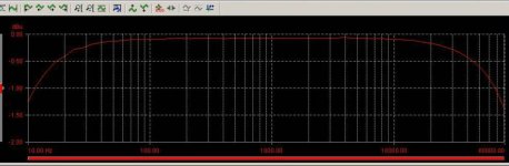

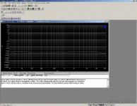
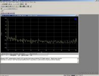
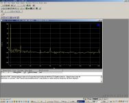
About MX50X2 test pattern.
The original design MusicalFidelity X-A50
It is a quasi complementary amplifier.
The name is very similar to MX50. But different circuit.
MX50X2 TEST: AP SYS 2700
The original design MusicalFidelity X-A50
It is a quasi complementary amplifier.
The name is very similar to MX50. But different circuit.
MX50X2 TEST: AP SYS 2700
Attachments
- Home
- Amplifiers
- Solid State
- LJM MX50 kit amp