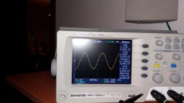
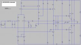
The image. And the test data.
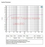
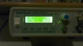
Test data: testing equipment: Audio Precision 2
Frequency response = 20 HZ - 25 k HZ - 0.2 DB
THD+N=0.002% 20hz-20KHZ 10W RMS 8 OHM
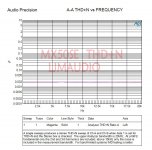
Test data: testing equipment: Audio Precision 2
Frequency response = 20 HZ - 25 k HZ - 0.2 DB
THD+N=0.002% 20hz-20KHZ 10W RMS 8 OHM
Attachments
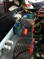
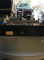
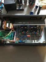
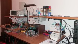
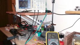
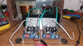
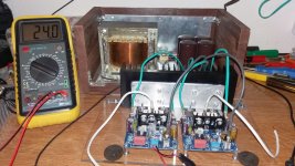
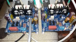
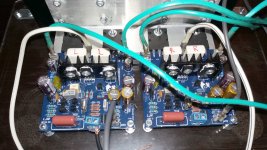
more pics
Hello,
What is the module with four transistors?
Thanks!
I'm surprised the bias current is only a small fraction what it probably should be.
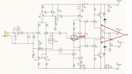
Bias setting using fixed resistors results in huge errors compared with the calculated values of what it should be. Therefore, if it is necessary to have fixed resistors for bias setting one must first solder precision 25 turn trimmer in place of the bias setting resistor, set the bias, desolder it and than measure the value on the trimmer, buy the appropriate value of the resistor and than solder it. Very complicated, time consuming process. Simply soldering calculated value resistor will never give anything remotely close to the calculated value.
The described procedure should be performed independently for each channel! Measured value on the trimmer for one channel will certainly be very much different than the value needed for the other channel.
330R + 1k pot. Insted of 1K metal resistor.The described procedure should be performed independently for each channel! Measured value on the trimmer for one channel will certainly be very much different than the value needed for the other channel.
I recommeded reading everyday practical electronics the was a artickle of this amplifier and fine tuning, a few mods for stabilatity. Wet elek. Caps removel. Good artickle for those intrested.
I think that LJM opted for the fixed resistor bias circuit in order to avoid setting procedure and make assembly simpler for the builder. To be honest, even with huge bias current errors this amp will sound very good. But if the builder want to have exact and precise bias level, trim pot is the way to go.
Hello! I've built the amplifier with modifications to the choice of spare parts. I used better transistor capacitors and resistors. I placed bias trimer. I pumped the amplifier with + - 40 volts. The result is fantastic!
Attachments
-
 MX50 SE bias.jpg349.8 KB · Views: 951
 -
 MX50 SE (9).jpg534.6 KB · Views: 591
 -
 MX50 SE (8).jpg775.8 KB · Views: 511
 -
 MX50 SE (7).jpg670 KB · Views: 489
 -
 MX50 SE (6).jpg704.1 KB · Views: 493
 -
 MX50 SE (5).jpg498.3 KB · Views: 526
 -
 MX50 SE (4).jpg870.4 KB · Views: 557
 -
 MX50 SE (3).jpg852.3 KB · Views: 652
 -
 MX50 SE (2).jpg905.1 KB · Views: 753
 -
 MX50 SE (1).jpg871.2 KB · Views: 783
Hi madel88,
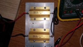
Can you give details about 4R dummy load resistors? Power rating, price, seller, etc...
Can you give details about 4R dummy load resistors? Power rating, price, seller, etc...
Hi madel88,
Can you give details about 4R dummy load resistors? Power rating, price, seller, etc...
The resistance is this:HS100 4R F ARCOL / Ohmite | Mouser Deutschland
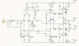
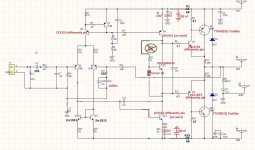
R30,C14 can't be correct connected🙂Hello! I've built the amplifier with modifications to the choice of spare parts. I used better transistor capacitors and resistors. I placed bias trimer. I pumped the amplifier with + - 40 volts. The result is fantastic!
R30,C14 can't be correct connected🙂
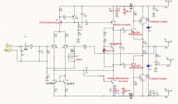
The schematic is wrong, the board is correct. I had seen it and checked it.
Please post the corrected😉The schematic is wrong, the board is correct. I had seen it and checked it.
Do you have hum with one shared power supply for the two power amps.
No 10R ground lift resistor.
No 10R ground lift resistor.
I see R24.Do you have hum with one shared power supply for the two power amps.
No 10R ground lift resistor.
- Home
- Amplifiers
- Solid State
- LJM MX50 kit amp