Any bias adjustment would depend on what current you calculate from the voltage drop across the output emitter (or rather collector here) resistors, R13,R20. It may only be a few mV, so measure voltage instead across both resistors in series, using the total 0.44R value and of course, Ohms law. Make certain that there is no signal or load connected when making DC measurements like this.
A CFP design should have around 13-20 mA bias current for optimal class B operation but it might be interesting to learn what LJM thought was optimal and what substituted transistors like your D1047/B817 copies could sound better with. I suspect they are nothing like the original specified transistor types (Sanken 2SA1186 and 2SC2343) or even original Sanyo 2SD1047/2SB817.
Supplying cheaper substitute components for a lower selling price may still work OK but how well they work is never discussed or advised in the Chinese kits of parts or prebuilt modules. It's going to cost a lot more to fix a problem like this by buying more parts for cost-cut kits so look for original spec or closest parts kits first, as these often directly affect performance at some level. Saving a few dollars on the kit price is a drop in the ocean of the finished amp and just not worth the grief. Check earlier posts in this thread for serious comments on sound quality.
I actually think LJM's designs are very good value and performance as they come but the copy-kits and often fake parts version seldom are - it takes quite some effort to trouble shoot the faults when they stem from unidentified bad component choices and faked subs.
Changing the input cap. won't make much difference at all. Calculate the small difference in the -3dB corner frequency for yourself - just more cost-cutting. No need to fit a trimpot unless you want to finely adjust the bias which probably requires surgery on the PCB and is unnecessary at this stage, where if you have a small stock of alternate resistors for the present voltage divider, other matters will be more important.
I couldn't say what headroom you need as that depends on speaker sensitivity and the SPL you are expecting to hear. To make meaningful measurements, you really need at least a 'scope and dummy load. A twenty watt amp goes pretty loud though, with say, 89 dB/1W/1m sensitive speakers but a realistic, comfortable room level of only 1-5W won't be a problem at all. Just don't expect to play dance music at neighbour-hate bass levels
Thanks for your reply Ian - much appreciated. DC voltage measures 1.6mV, so i guess that means a current of about 3.64mA? A bit on the low side..where to from here I wonder?
This is all good education for me! Cheers.
This is all good education for me! Cheers.
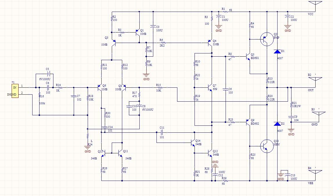
I'm surprised the bias current is only a small fraction what it probably should be. I've linked a schematic posted at #4, assuming it's still applicable to your kit. http://www.diyaudio.com/forums/atta...771d1343053135-ljm-mx50-kit-amp-schematic.jpg
Locate and check that resistors R10, R22 & R19 are the correct values in their locations so that the voltage divider formed can set the right bias current. If necessary, measure the resistors in position with the power off. Are they in the same positions and giving similar current in both channels if you have a stereo pair? What is the voltage across C106 or between the bases of Q5, Q9? It should be in the region of 2.7V if those transistors are in fact darlingtons as shown on the schematic. If they are other than darlingtons like BD681/682, that could be the problem there.
It's a very unusual arrangement for an output stage, assuming that's what it really is and not a false schematic as we had with the L12-2 model. .
My reading across the 105 cap is 1.3V. The 2 resistors off either end of that cap are 1k and 100 ohms. It's a bit tricky to trace as it is difficult to get to the underside of the pcb without dismantling the amp. It appears there are many diff values and components on this board (MX50 se version) compared to the original schematic.
It's a very unusual arrangement for an output stage, assuming that's what it really is and not a false schematic as we had with the L12-2 model. .
It's almost certainly erroneous.
Chinese kit makers for some reason love the B649/D669 combination even though the original source is well out of production, and you'll find that these are the transistors in position as the driver. Many of the images in this thread and even posted by ljm show that to be the case as well.
OK, here is the SE version schematic, or rather a reverse engineered one borrowed from this thread: http://www.diyaudio.com/forums/solid-state/273821-mx50se-ljm-2015-a.html
http://i.imgur.com/upb3ujB.png
I suggest you read that short thread since you have the SE version and the question has been raised before. Thanks for the hint, mt490, you're right about those generic copy D669/B649 transistors. They also are available cheaply as D667/B647 in a TO92L package and they're everywhere because they're all quite cheap and probably sell on the reputation and similar logo to the very popular original Hitachi/Renesas driver types.
As the drivers aren't darlingtons, the bias voltage across C106 should indeed be around 1.3V, so that's OK for a CFP output stage but are R21,22 both 1k? It would screw up the bias current if they weren't but you still could need to trim the resistors as shown with an additional 68R in the MX50 schematic, which likely increased the current to a more correct level.
Last edited:
Although I haven't played with this model specifically, if the output emitter resistors are 0R1 then I would probably initially aim for the 11mV point for biasing IME. This is a bit higher than the Class-B optimum in published literature for CFP but higher does seem to give a 'safer' sound than holding the threshold.
Perhaps one notable example is the P3A - it's very conservatively in elevated bias yet not a super high feedback design, but its sound seems to be well received.
Perhaps one notable example is the P3A - it's very conservatively in elevated bias yet not a super high feedback design, but its sound seems to be well received.
Last edited:
The emitter resistors are most likely 0.22R and the normal CFP bias for those is ~13 mA. 11mV would be on the low side according to Self so I don't think there would be any problem. In a very good low distortion design, 13-20mA will give lowest THD and sound excellent. In simpler designs where THD is higher, it seems you can use higher bias to advantage and as you say, the P3a is an example of that approach and a high bias of 70 mA is recommended - the sense transistor is not attached though and that changes the thermal compensation slope considerably.
Driver operating temperature range is important in CFP designs. It provides the thermal compensation slope and thus controls thermal stability. The driver current varies with power so it's not like an EF stage where the driver's own bias current holds its temperature virtually constant and you can almost do as you please with the fixed driver bias - assuming they are not attached to the output transistors or their heatsink.
Depending on where the temp. sense transistor is mounted, bias here should be running close to the designed range of current for safety reasons at least. From previous experience with LJM CFP designs, he uses 10 -20 mA with 0.22R and I'd stay within that range unless he suggests otherwise.
An externally hosted image should be here but it was not working when we last tested it.
An externally hosted image should be here but it was not working when we last tested it.
An externally hosted image should be here but it was not working when we last tested it.
diy with mx50 what tranformer/curret/ i need for 80watt 6ohm speker ????
Toroidal Transformers
An externally hosted image should be here but it was not working when we last tested it.
??????????????????thk
Last edited:
An externally hosted image should be here but it was not working when we last tested it.
Specification:
Supply Voltage: + -15v to + -45v
Output Power: 100W8R (+ - 42v)
An externally hosted image should be here but it was not working when we last tested it.
An externally hosted image should be here but it was not working when we last tested it.
Supply Voltage: + -15v to + -45v
Output Power: 100W8R (+ - 42v)
diy with mx50 what tranformer/curret/ i need for 100watt 4 ohm speker ????
Toroidal TransformersAn externally hosted image should be here but it was not working when we last tested it.??????????????????
thk
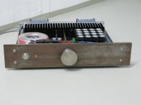
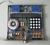
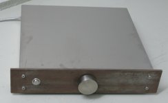
my MX50SE
i did this amp a while ago for my friends desktop.
since i wanted something different for the front i decided to take corten-steel
that was bathed in bathroom-cleaner for a few hours
and then dry-cloth-polished: fantastic stains!.
the volume knob is an abused v2a doorknob.
great amp; thanks to LJM!
i did this amp a while ago for my friends desktop.
since i wanted something different for the front i decided to take corten-steel
that was bathed in bathroom-cleaner for a few hours
and then dry-cloth-polished: fantastic stains!.
the volume knob is an abused v2a doorknob.
great amp; thanks to LJM!
Attachments

Nicely built, looks very organised. Did you compare the sound quality with any of the commercial offerings?i did this amp a while ago for my friends desktop.
since i wanted something different for the front i decided to take corten-steel
that was bathed in bathroom-cleaner for a few hours
and then dry-cloth-polished: fantastic stains!.
the volume knob is an abused v2a doorknob.
great amp; thanks to LJM!
Regards
Bilal
@Bilal,
thanks for the flattering words.
no, this amp is just for office use driving a pair of "neat continental®" speakers fed by a minimac.
thanks for the flattering words.
no, this amp is just for office use driving a pair of "neat continental®" speakers fed by a minimac.
I received my boards yesterday and installed them with an Antek 300VA 28V AC transformer with 45,000 uf per bank of capacitance. Sounds much better than it should considering the cost. Ideal first project for a diy'er.
Congratulations on the good assembly. Looks very careful, excellent AC filtering. Very good layout shortening the connections. Beautiful and professional product!more pics
- Home
- Amplifiers
- Solid State
- LJM MX50 kit amp