I'm very new to building amps and power supplies but need to make a start somewhere so I purchased this amp because the designer is here and everyone else seems willing to help even if I ask a dumb question. Here is my first ones!
I would like to have most of the parts on hand when the amp boards arrive and I've found this transformer:
Avel Y236652 250VA 25V+25V Toroidal Transformer
Would this transformer be suited for this amp? If not what should I use to give the best performance without blowing up the amp?
Thanks in advance for the help.
It is very good, no problem.
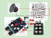
Pay attention to You will also need a rectifier + filter capacitance. Of course, the radiator is needed.
This will allow you to experience the HIEND effect.
Refer to figure. Similar.
Attachments
It is very good, no problem.
Pay attention to You will also need a rectifier + filter capacitance. Of course, the radiator is needed.
This will allow you to experience the HIEND effect.
Refer to figure. Similar.
Thank you very much for the input. What would be the optimal transformer in terms of VA and Volts AC? I have a little more $$ and I may as well invest now so I don't have to upgrade later.
I replaced transistors 649 and 669 on 2SA1930 and 2SC5171 having turned them on 180 degrees, чтб B C E coincided. There were more echoes, warmer sound, especially it was pleasant on the high and average frequencies, it is less than sharpness. At 649 and the 669th sound is crushed, plastic, top cut hearing, the middle is failed, echoes are swallowed. After replacement it is necessary to adjust standing current!
I replaced transistors 649 and 669 on 2SA1930 and 2SC5171 having turned them on 180 degrees, that B C E coincided. There were more echoes, warmer sound, especially it was pleasant on the high and average frequencies, it is less than sharpness. At 649 and the 669th sound is crushed, plastic, top cut hearing, the middle is failed, echoes are swallowed. After replacement it is necessary to adjust standing current!
Please advise!
I have this rectifier board from a previous build:
http://www.amazon.com/gp/product/B00C2P63CA?psc=1&redirect=true&ref_=oh_aui_detailpage_o02_s00
It uses Sanyo 2200uf caps rated @ 35v and the rectifier is rated at dual 35v
Here is the data sheet for the rectifier:
http://www.dccomponents.com/products/Rectifiers/Bridge/BR3505L-BR3510L.pdf
My question is can it be used for this kit with a 28-0-28 transformer until I upgrade to a 63v board or should I not even attempt to connect it up? I would like to avoid and damage to the board or start a fire!
Thanks
At 28v you'd really be pushing the limits of the filter caps rated at 35VDC. Even at the typical ac supply of 24V, you'd max out at about 34VDC, just shy of the rated 35v caps. I'd either get another board with higher rated caps, or swap out the filter caps for ones rated at 40VDC. If you intend to use the 28-0-28 xformer, than I'd go with 63VDC rated caps. Better safe than sorry. A lot too depends upon how hard you intend to push the amp. 🙂Please advise!
I have this rectifier board from a previous build:
http://www.amazon.com/gp/product/B00C2P63CA?psc=1&redirect=true&ref_=oh_aui_detailpage_o02_s00
It uses Sanyo 2200uf caps rated @ 35v and the rectifier is rated at dual 35v
Here is the data sheet for the rectifier:
http://www.dccomponents.com/products/Rectifiers/Bridge/BR3505L-BR3510L.pdf
My question is can it be used for this kit with a 28-0-28 transformer until I upgrade to a 63v board or should I not even attempt to connect it up? I would like to avoid and damage to the board or start a fire!
Thanks
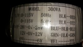
Transformer questions
Help Please! I may have received the wrong transformer. 😕 I swear when I ordered it the specs said 115-0-115 input with secondaries as stated on the label. Can this transformer be used for USA 115v and if so how? Any loss of output? A giant thanks to anyone that can help. 😀
Help Please! I may have received the wrong transformer. 😕 I swear when I ordered it the specs said 115-0-115 input with secondaries as stated on the label. Can this transformer be used for USA 115v and if so how? Any loss of output? A giant thanks to anyone that can help. 😀
Attachments
Help Please! I may have received the wrong transformer. 😕 I swear when I ordered it the specs said 115-0-115 input with secondaries as stated on the label. Can this transformer be used for USA 115v and if so how? Any loss of output? A giant thanks to anyone that can help. 😀
Okay I answered my own question so I'll add the basic information to help anyone facing the same situation feel free to correct me if I'm wrong.
Dual Primaries: connect in parallel, red to red and black to black for USA 115v then the red goes to Hot/black on the mains and the
black to the neutral/white on the mains. 50Hz windings can be used on 60Hz but not the other way around.
Hi Everybody.
Can I have some help here please as I am a bit confused😕
I want to build a 6 channel amp for tri-amping my speakers using the mx50 modules. My toroid is 625VA 35VAC (actually I have 2 of these toroids on hand).
Is this transformer rating too high? I have been advised that 28VAC is about as high as you should go but in doing some reading around here, I'm not convinced that this is the case.
Can anyone clarify this for me?
And also, can anyone recommend a good rectifier/power supply board to use with this build?
Many thanks.
I have no experience with this module. But based on LJM's info on his taobao shop (in Chinese), the maximum input voltage for MX50 SE board is 2 x 12VAC to 2 x 32VAC (i.e. DC +- 15v to +- 45V)
Regards,
Regards,
Hi Everybody.
Can I have some help here please as I am a bit confused😕
I want to build a 6 channel amp for tri-amping my speakers using the mx50 modules. My toroid is 625VA 35VAC (actually I have 2 of these toroids on hand).
Is this transformer rating too high? I have been advised that 28VAC is about as high as you should go but in doing some reading around here, I'm not convinced that this is the case.
Can anyone clarify this for me?
And also, can anyone recommend a good rectifier/power supply board to use with this build?
Many thanks.
Thanks Maxi.
Looks like I am just a little too high with my existing toroid at +/- 50V. Darn!!!🙁
Looks like I am just a little too high with my existing toroid at +/- 50V. Darn!!!🙁
I have just received the MX50.2 ordered Jan 6th. A quick check shows the R22 emitter resistors required by the PCB have been replaced by R15 in the parts supplied. Is there a modified schematic for the MX50.2 (with four output transistors)?
Paulcar
Paulcar
there is some errors on marks of pcb. the resistor that connecting trs Q3 with vcc is marked 150 Ω,must be 100 Ω ,the resistor that connecting trs Q4 with vcc is marked 100 Ω that one must be 150 Ω. if y do this changes y will get a not harsh and very decent sound.
also must change the 16v470u feedback capacitor to one 6.3v1000u , if y want the bass come back..
Thanks for those tips odisy! I too found the MX50 SE a little too harsh for my taste. How did you arrive at the resistor changes? All the schematics I can find show Q3 resistor (R2) as 150R and Q4 resistor (R3) as 100R, and this is how it is marked on the PCB.
I make a few changes and i take a very decent sound from this little amplifier.Resistors R2 and R3 both 150R, C3 (100uf) compensation capacitor as it is but 16v rating, C11 (100pf) miller efect as it is but simple ceramic 50v rating, C7 (470pf) change to 681pf 50v ceramic ,100nf mkt under board parallel to C1 & C12.If u like the sound after that can change the output transistors to better ones.Good luck..
I've just finished making this amp. I have the 1047/817 transistors and am using a 2 x 14.5V AC 200VA transformer. The amp is very quiet, and It runs very cool, not even warm! It sounds very good, but I'm finding it could be smoother sounding in the top end. What of the many suggested modifications would builders think best for my set up?
Thanks in advance.
Thanks in advance.
What bias current setting have you used? It probably should be fairly cool as it is a CFP design but if bias was still too low, that would certainly give rise to some harshness in the sound. 2 x 14,5V AC would give about 20V DC unloaded rails. That seems a very small supply for MX50s but you may get 20W/8R output.
As there is no bias adjust provided I have just left it as stock. Do you think I should introduce a trimmer to adjust bias? I was also thinking about the input capacitor value (drop from 3.3 to 2.2?) and the other suggestions a few posts back? Perhaps I am expecting to much of my low voltage/high current transformer and am running out of headroom?
- Home
- Amplifiers
- Solid State
- LJM MX50 kit amp