IN V10, what does C6 do? its tied to the feedback loop, would it be by any chance audible?
It is needed to make the Lpad working in AC but not in DC, for which total feedback is needed. It is audible, sure it is. It MUST be a high-quality NP capacitor.
Hi Marigno,
I have a 250va 28v ac transformer available. My speakers have good efficiency and 4 ohms. I rarely listen to loud music, so for me the transformer is sufficient.
The calculation is simple: usually 50Vdc=25W/8Ohm, 100Vdc=100W/8Ohm, 141Vdc=200W/8Ohm, 200Vdc=400W/8Ohm.
With your transformer, you would get a power of 15W/8Ohm
Nowadays a solid-state 15W is too low a power in order to follow the high dynamic of HiRes music unless you have very very high-efficiency speakers.
However, the L20 starts working at a very low voltage, if I well remember; there is no Zener in the circuitry so everything is linear with the voltage of the PSU. If you have suitable speakers You can do it!
Thanks. Would a film cap (WIMA etc) work better?
It could! Do you have room for it?
Hi marigno,
with the 28vac transformer, will give around 39-0-39vdc. So 78vdc, is that correct ??
There will be a power limitation caused by the power of 250va x efficiency
with the 28vac transformer, will give around 39-0-39vdc. So 78vdc, is that correct ??
There will be a power limitation caused by the power of 250va x efficiency
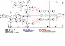
Here is the complete mods that can be done on the 9.2 board itself.
Caution with Rb2/3/4/5, they will increase the temperature of TR2/3/4/5, check them.
Super caution with the green mod.
There is no room to add a Cascode to the VAS.
To achieve the NSCB operating mode, the output pairs must be removed. Too messy. I do not recommend it.
Caution with Rb2/3/4/5, they will increase the temperature of TR2/3/4/5, check them.
Super caution with the green mod.
There is no room to add a Cascode to the VAS.
To achieve the NSCB operating mode, the output pairs must be removed. Too messy. I do not recommend it.
Attachments
L20 V9.2 VBE Mods
Looking at V10 they have added VBE resistors of 100 ohms on the output pairs. Being involved with high current switching circuits, having no pull off resistors is a very bad idea regarding turn off speed and leakage currents etc.
As the weather is so rubbish I got down to modifying the amp - introducing VBE resistors on output transistors and multi turn trimmers. Sound is so sweet and transparent even at room shaking volume! I set the biases at 65mA Only snag is MDW was a constant distraction and on moving something there was a small puff of smoke! Not sure if it was the iron but the 200mA fuse in the multimeter measuring the quiescent on RH channel was blown. Can't see anything and I left on soak overnight and both DC offsets are only 4mV and PSU is rock solid. I am assuming it might have been a temporary overload on a pcb track - after all the fuse was only 200mA. I'm sure the sound at high levels especially is improved.
VBE resistors were 150 Ohms not 100 so as not to upset the bias stability too much. The VBE multiplier had to be increased as the drivers would be on more. Trimmer was 200k multiturn causing very gradual adjustment. See diag
Attachments

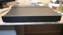
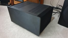
Some months ago I built an ultra-thin version of the L20 V9.2, with a very soft power supply: 65+65Vac 200VA in total for both channels, and a small heat-sink.
I made some mods to the original values: REs 0.1Ohm resistor in place of 0.22Ohm and recalculated the feedback network with 33KOhm, 1KOhm, 150uF NP, in place of original 10KOhm, 330Ohm, 1mF; the input cap was replaced by a poly 3uF one.
I could trim the bias at a very low value, almost B-class, without cross-over distortion.
The amp was good to be my lab amp, with 8Ohm speakers, but not able to drive my Acoustat 1+1, it overheated.
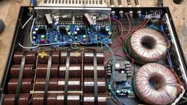
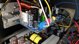
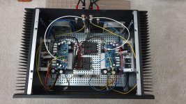
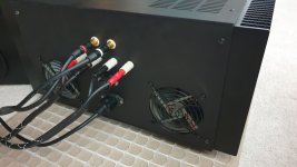
In order to drive my Acoustat 1+1, I decided to move the two boards to a bigger cabinet (HiFi2000 "Dissipante" 5U/300mm), and build a dual mono amp using two LLC Switching power supply +/-70V 1000W (eBay) and two speakers protection board 30A 110/220Vac (eBay), where the relays of each board are paralleled to serve one channel. I doubled the aluminum angulars in order to achieve better thermal conduction from final pairs to the heat-sink. The cabinet is connected by a dual ground coupler to the central 0V of each channel.
The two power supplies are very tough, and the first happening, after raising the volume, was the blowing of two final transistors, a PNP each channel. So I decided to put in place again the 0.22Ohm REs and to insert a 2.2Ohm resistor between the driver's emitter and the final pairs' bases. The bias was increased to the original value, almost 140mA total, 200mA for the whole board.
Then, the second happening was the triggering of the thermal protection on the power supplies: they have two heat-sink each, with horizontal fins, that is not a good idea, in order to dispose of the heat. The triggering happens even when idle, once the cabinet is closed. So I put in place two 92mm fans (Noctua Redux), powered by the 15V outlet of each power supply, crossing a 150Ohm resistor. Now, when idle, the whole cabinet is almost cold, and, when listening, depending on the volume, the thing warms up but never becomes hot.
The result: despite the switching power supply, I must say I love the sound, clear and authoritative.
BTW: I changed the final pairs to MJL3281A/MJL1302A, but just because I had some in my drawers.
I made some mods to the original values: REs 0.1Ohm resistor in place of 0.22Ohm and recalculated the feedback network with 33KOhm, 1KOhm, 150uF NP, in place of original 10KOhm, 330Ohm, 1mF; the input cap was replaced by a poly 3uF one.
I could trim the bias at a very low value, almost B-class, without cross-over distortion.
The amp was good to be my lab amp, with 8Ohm speakers, but not able to drive my Acoustat 1+1, it overheated.
In order to drive my Acoustat 1+1, I decided to move the two boards to a bigger cabinet (HiFi2000 "Dissipante" 5U/300mm), and build a dual mono amp using two LLC Switching power supply +/-70V 1000W (eBay) and two speakers protection board 30A 110/220Vac (eBay), where the relays of each board are paralleled to serve one channel. I doubled the aluminum angulars in order to achieve better thermal conduction from final pairs to the heat-sink. The cabinet is connected by a dual ground coupler to the central 0V of each channel.
The two power supplies are very tough, and the first happening, after raising the volume, was the blowing of two final transistors, a PNP each channel. So I decided to put in place again the 0.22Ohm REs and to insert a 2.2Ohm resistor between the driver's emitter and the final pairs' bases. The bias was increased to the original value, almost 140mA total, 200mA for the whole board.
Then, the second happening was the triggering of the thermal protection on the power supplies: they have two heat-sink each, with horizontal fins, that is not a good idea, in order to dispose of the heat. The triggering happens even when idle, once the cabinet is closed. So I put in place two 92mm fans (Noctua Redux), powered by the 15V outlet of each power supply, crossing a 150Ohm resistor. Now, when idle, the whole cabinet is almost cold, and, when listening, depending on the volume, the thing warms up but never becomes hot.
The result: despite the switching power supply, I must say I love the sound, clear and authoritative.
BTW: I changed the final pairs to MJL3281A/MJL1302A, but just because I had some in my drawers.
Attachments

Thanks for your appreciation!
This is the schematic which I missed posting last time. The brown items are the mods I made, the red items are to be done when I have time.
The L20 is connected to the Audio-TV set and is on almost the whole day; its temperature is very low at a normal listening volume, almost cold with the two fans.
I learned that fans are mandatory in a power amplifier to let the inside cool down.
Attachments

Please note that L20SE and L20-9.2 are almost the same having the same issues. Therefore, medicine is the same.
There are two problems with this amplifier:
1. Noise riding on top of signal (see my post >>HERE<<)
2. Nonexistent bias
As a consequence this amplifier sounds dull.
The both problems have been addressed here but solutions are burried in a large number of posts. Problem 1. is due to too high gain, low bias causes crossover artefacts.
All you have to do is shown on the image below:
1. Replace 330R with 470R to increase feedback (and reduce gain)
2. Replace the 4K7 resistor with 5K potentiometer and adjust its resistance so that voltage between the output and emitter of any output transistor meassures 9-12 mV. Measurement points are indicated with 1 and 2 on the image below.
After the above simple changes, noise and crossover artefacts will wanish.
Here we are finally!
Thank you, @Berlusconi !
I don't know how it is possible: my L20 V9.2 has zero bias, and the triangular wave is perfect.
I didn't get any measurements driving the amp to power, basically because I don't have any power load.
But I will, I have to buy suitable resistors and put them in a can with oil.
Unfortunately, I'm close to flying to Italy for a long stay, so I don't have time to carry on the measurements.
What I want you to notice is the R polarizing the NPN pre-drive. It is likely paralleled with the 2nd CCS. It is a weird circuit; usually, the sequence from the bottom is VAS, xVbe, CCS. It had to be investigated. For sure that R widens the open-loop bandpass.
I'm now reading Bob Cordell's "Designing Audio Power Amplifiers", where he discusses how to bias the final pairs (page 101).
Regarding the noise and the gain, I didn't notice anything bad, perhaps measuring the noise floor, the ratio S/N could not be the best.
- Home
- Amplifiers
- Solid State
- LJM L20 V9.0 Amplifier