Not Fluent on Scotch ? Aye
Lets Look at the evidence?.
Sadly cannot drink hard stuff or even Iron Brew. It is the only country in the world that does not have Cola as its number one soft drink. (from a quiz)
Also got the correct answer to the name of a Scottish Fish that begins and ends with a K,,
I do have Ecosse cables in and around the system, Mains in particular works well.
I did have Haggis for evening meal last saturday.😀
I met and Irishman Welshman and Scotsman in a Manchester pub and the aforesaid Mr McCracken unusually shouted " Drinks all round on me for the whole night."
The following morning I read that an Irish ventriloquist was found strangled ,
ps I had volunteered to do missionary work in Scotland once.
Well that was almost a year ago.,,,,,LOL.
Happy whatever it is to you and once again thanks for previous help.
PS I am going back to a two way speaker design so current amplifier may be starting to worry...LOL. again.
Dave CEO Dogsbody and all things superaudiosales4u...
Hi all, I just bought a pair of L20 V9.2 amps - question: what's the input voltage to feed these modules ? (I assume it's not 0dB / 775mV).
Thanks & cheers 😉
Thanks & cheers 😉
I found that these amps work quite well on the 136kHz amateur band. The Zobel network on the output needs alteration, the 100nF should be changed to10nF (the one in series with the 10ohm resistor). By fitting the 2SA1930 & 2SC5200 output transistors I can get at least 200W out at this high frequency with 300W DC input.
I opted for a 1uF polypropylene capacitor in series with the output to avoid operator ****-ups and the nominal +/- 35 supply has a 1 second delay by shorting out a 220ohm resistor initially in series with the transformer primary.
The output transistors are directly fixed to seperate heatsinks so there's a little constructional conundrum isolating these from the chassis but it saves cooking them.
I've tried other LJM amps (they're not designed for this frequency!) and they are not up to this standard.
I think it needs about up to 1.5V rms of input voltage for full output power on +-65 volt rails and 8ohms loadHi all, I just bought a pair of L20 V9.2 amps - question: what's the input voltage to feed these modules ? (I assume it's not 0dB / 775mV).
Thanks & cheers 😉
I tried it on +/- 50V unregulated and it gives no more output than +/- 35V unregulated, bear in mind this isn't audio though. Input is about 1V rms for +V to -V full output.
I think there is no increase in output when going from +/-35V to +/-50V supplies because of the odd VAS loading arrangement. The VAS load is a constant current source in parallel with an unbootstrapped 33k resistor. Obviously this is going to limit the VAS voltage swing. Someday I'm going to mod one of my boards to do away with the 33k resistor, so that the only VAS loading is via the constant current source. This should lead to higher output with higher voltage supply rails and lower distortion.
My take on the LJM V9.0 amps:
1st round: hooked them up to a +/- 45VDC supply, sound was horrid. Not sure if it was due to zero bias or other reasons 🙁
2nd round: this time I applied some changes:
Overall, it is an excellent bang for the buck !
Cheers, Yair
1st round: hooked them up to a +/- 45VDC supply, sound was horrid. Not sure if it was due to zero bias or other reasons 🙁
2nd round: this time I applied some changes:
Removed 2 of the 4 pairs of output transistors (4 pairs are not necessary in such low voltage).
Added 270R resistor in series with the 9K bias resistor (the one on B-C legs), which increased the bias to 10mV across two resistors.
Changed input coupling cap to something nicer.
Changed input series resistor from 2.2k to 634Ohms, which extended the highs.
Overall, it is an excellent bang for the buck !
Cheers, Yair
ljm l20 9.2
interesting observations as today I re installed my boards after a few months away due to illness and poorer eyesight and have had only light listening via some commercial amps.
Initially I thought the standard V9.2 assembled boards were a bit thin sonically especially at the bass end when using Volt/SSspeakers.
Since then Ive modded almost every part with theoretically higher quality bits,
Obviously I changed almost all the resistors to Vishay foils and each exchange provided an improvement. I am using sacd level and/or 24/96 as a source. The sonic changes to a cd input were almost as noticable except the slight metalic ringing was still a challenge. The bass was evidently rolled off and removing the dc blocking cap makes a difference.
I then swapped Ecaps to Panasonics but was not convinced by their slightly improved sonics with a slightly more solid bass/midrange ?. I havent bypassed these Ecaps with 100nf s yet.. I think It has to be Silmics with this board.?
My main suspicion of the sonics is down to 1uf tantulums in two places.Never liked them or that Naim sound???
Ive since purchased a set of polyprops 1uf for replacement in either of those two locations. Will report if my eyesight improves.
Raising the value of 9k1 was suggested by the late AndrewT to increase that current flow ? but I never got around to it. My amps do run very cold and I have masses of heatsink,
I was going to do a number of 68R vishays but cannot obtain them reasonably.
Cannot understand changing 2k2 to lower value making sonic improvement if same type of resistor was used.
Must admit I need to clear out some of my Used/blown? ljm boards.
Dave
Let's just say, hypothetically, that somebody were to be stupid enough to connect the supply rails reverse polarity on one of these and notice a brief moment of the amplifier releasing some smoke in the vicinity of the + rail connection (grrrr), what would they cook?
I really ought to not work on stuff like this late at night.
I can't find circuit diagram. I'm hoping (though doubtful) that I've killed just a diode or 2.
Rails were at +-60vdc 🙁
I really ought to not work on stuff like this late at night.
I can't find circuit diagram. I'm hoping (though doubtful) that I've killed just a diode or 2.
Rails were at +-60vdc 🙁
Its so easy to do. Been there, done that, and got away with it. Mainly because I use a power supply which disconnects itself instantly as soon as a preset current limit is reached; I usually start with 250mA for initial power up. I'm thinking about putting high current diodes in the +ve and -ve lines of future power amp designs. When everything is set up the diodes can be shorted out.
Will try swapping the diodes today if I have some suitable spare. Annoying as the amp has been used a bit already and works well, was just shifting to another case for it.
Diodes replaced and it appears to be alive!
The 8" driver that I accidentally knocked off the bench while working on the amp didn't fair too well. I'm glad it was borderline scrap anyway.
The 8" driver that I accidentally knocked off the bench while working on the amp didn't fair too well. I'm glad it was borderline scrap anyway.
Adding a buffer to the VAS
Hello,
first of all I have to say I like Douglas Self's theories a lot and the modification I made were inspired by reading DS.
I'm working on the 9.2 board.
I just finished to assemble two couples of L20 V10, one couple is almost untouched original, I modified only the Re's by putting 0.1Ohm in place of 0.2Ohm resistors and added a 0.23uH inductor bypassed with 10Ohm 5W resistor; these boards are powered with 126V 240VA total for both channels (very soft, weak power supply), the result is no bad at all for a main analogic amplifier only one unit high.
The second couple of boards is like the first one but I changed the final couples with 11 (per channel) couples of 2SC3264/2SA1295; these boards are powered individually with 152Vcc, single transformer 625VA. Very impressive, the sound is very good on the Acoustat 1+1 Mediallion Mod.C even with zero bias. By the way, I had to add a 47pF silver mica capacitor paralleled to the 12pF Cdom, the field generated by the Acoustat lead the board to auto oscillation.
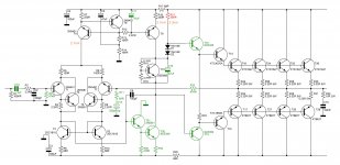
I think the old version 9.2 should be better that the new 10 one, that has two less transistor, i'm sure they removed the two Sziklay CFP leaving in place just two regular transistor. I modified the V9.2 essentially in the VAS by adding a buffer. Take a look to the schematic, the green components are those I modified. So far I could test only one channel at time, stable a 135V and it seems ok. If everything is ok I will replace the V10 boards in the big main amplifier. Did anybody try to add a buffer to the VAS? You could add a cascode too but there is no space on the board and the pcb tracks are so delicate that it is very easy to damage them. So, no cascode for me! Everyone noticed that the VAS is loaded in an odd way, I think the 33KOhm resistor does not limit the swing, just reduces the amplification but enhances the open loop bandwidth.
Hello,
first of all I have to say I like Douglas Self's theories a lot and the modification I made were inspired by reading DS.
I'm working on the 9.2 board.
I just finished to assemble two couples of L20 V10, one couple is almost untouched original, I modified only the Re's by putting 0.1Ohm in place of 0.2Ohm resistors and added a 0.23uH inductor bypassed with 10Ohm 5W resistor; these boards are powered with 126V 240VA total for both channels (very soft, weak power supply), the result is no bad at all for a main analogic amplifier only one unit high.
The second couple of boards is like the first one but I changed the final couples with 11 (per channel) couples of 2SC3264/2SA1295; these boards are powered individually with 152Vcc, single transformer 625VA. Very impressive, the sound is very good on the Acoustat 1+1 Mediallion Mod.C even with zero bias. By the way, I had to add a 47pF silver mica capacitor paralleled to the 12pF Cdom, the field generated by the Acoustat lead the board to auto oscillation.
I think the old version 9.2 should be better that the new 10 one, that has two less transistor, i'm sure they removed the two Sziklay CFP leaving in place just two regular transistor. I modified the V9.2 essentially in the VAS by adding a buffer. Take a look to the schematic, the green components are those I modified. So far I could test only one channel at time, stable a 135V and it seems ok. If everything is ok I will replace the V10 boards in the big main amplifier. Did anybody try to add a buffer to the VAS? You could add a cascode too but there is no space on the board and the pcb tracks are so delicate that it is very easy to damage them. So, no cascode for me! Everyone noticed that the VAS is loaded in an odd way, I think the 33KOhm resistor does not limit the swing, just reduces the amplification but enhances the open loop bandwidth.
Attachments
Back to the build,
I modified the circuitry by adding a 50k 25turn pot across the 1k BE resistor of the Vbe multiplier (Q8), so i could fine tune the bias current. It works great, and i tried a lot of different values but settled at about 20mA per output pair.
While comparing with the other channel, which had zero output bias, I COULDN'T tell them apart, they sounded exactly the same to me (with soft music as a source). But when i tried with a pure 1kHz sine wave, i thing there was a slight raspiness in the no bias channel, but nothing too obvious. Anyway, seems some bias helps, and the amps sound fantastic, running off 60 Volt rails.
Now the problem is that the bias is very dependent on the heatsink temperature. When i start the amp up (cold heatsinks), the bias current is where it is supposed to be, exactly where i set it, at about 20mA per pair. As the heatsinks slowly warm up (without input signal), the bias settles at around 5mA per pair. If i play some music for a while and the heatsinks get real hot (to the point of no touchy), the bias almost disappears (about 1ma per pair). As the heatsinks slowly return to just warm, the 5mA bias also returns! Go figure....
Is this normal? I have checked everything, all output transistor are firmly attached to the heatsink, and are warming up at the same rate, including the bias control transistor (Q8). Shouldn't the bias be more stable? Am i missing something?
Please, give me some light. Is the bias supposed to be setup when the amp is idling or when it is real hot. Does this behavior indicate a problem with my thermal feedback?
quite normal, Q8 is compensating for thermal runaway. Set your bias with the sinks at 35-40c... Just make sure the OP devices have good thermal contact with the sinks.
Hello,
first of all I have to say I like Douglas Self's theories a lot and the modification I made were inspired by reading DS.
I'm working on the 9.2 board.
I just finished to assemble two couples of L20 V10, one couple is almost untouched original, I modified only the Re's by putting 0.1Ohm in place of 0.2Ohm resistors and added a 0.23uH inductor bypassed with 10Ohm 5W resistor; these boards are powered with 126V 240VA total for both channels (very soft, weak power supply), the result is no bad at all for a main analogic amplifier only one unit high.
The second couple of boards is like the first one but I changed the final couples with 11 (per channel) couples of 2SC3264/2SA1295; these boards are powered individually with 152Vcc, single transformer 625VA. Very impressive, the sound is very good on the Acoustat 1+1 Mediallion Mod.C even with zero bias. By the way, I had to add a 47pF silver mica capacitor paralleled to the 12pF Cdom, the field generated by the Acoustat lead the board to auto oscillation.
I think the old version 9.2 should be better that the new 10 one, that has two less transistor, i'm sure they removed the two Sziklay CFP leaving in place just two regular transistor. I modified the V9.2 essentially in the VAS by adding a buffer. Take a look to the schematic, the green components are those I modified. So far I could test only one channel at time, stable a 135V and it seems ok. If everything is ok I will replace the V10 boards in the big main amplifier. Did anybody try to add a buffer to the VAS? You could add a cascode too but there is no space on the board and the pcb tracks are so delicate that it is very easy to damage them. So, no cascode for me! Everyone noticed that the VAS is loaded in an odd way, I think the 33KOhm resistor does not limit the swing, just reduces the amplification but enhances the open loop bandwidth.
In your Darlington VAS modification what is the value of R34 that you used? (It is not marked on the schematic.)
Sorry for that. I'm not home so can't check for the value of R34. What I remember, it should be around 100Ohm. I will be able check it not so shortly, let's say a couple of weeks.
Sorry for that. I'm not home so can't check for the value of R34. What I remember, it should be around 100Ohm. I will be able check it not so shortly, let's say a couple of weeks.
Ok. Thank you. I'll wait for the reply. I have a different amplifier in the chassis right now anyways.
- Home
- Amplifiers
- Solid State
- LJM L20 V9.0 Amplifier