the value of R34 is 68Ohm.
Do you recall where you connected the ground for T31 when you made the modification and added the MJE340 (T30)?
I soldered a wire on top of R3's gnd side. R3's original value is 10KOhm.
Be very careful when modifying, the copper tracks of the PCB are very very delicate.
To power up the assembly for the first time, you should use a variac!
The mod enhances the V9.2 performances and, in the V10 (no triplet output), it is mandatory, if you want to obtain a HiFi amplifier.
Be very careful when modifying, the copper tracks of the PCB are very very delicate.
To power up the assembly for the first time, you should use a variac!
The mod enhances the V9.2 performances and, in the V10 (no triplet output), it is mandatory, if you want to obtain a HiFi amplifier.
marigno; said:To power up the assembly for the first time, you should use a variac!
I don't have a variac but I do have a Dim Bulb Tester and a variety of different voltage transformers. I usually start with the minimum voltage that the amplifier will operate at. I even do first power up with a current limited low voltage laboratory supply (+/- 18V) in some cases. The lab supply works ok powered from a 60W DBT too.
marigno; said:Be very careful when modifying, the copper tracks of the PCB are very very delicate.
Yes. With most of these kits the copper thickness is very very thin. And the through hole copper plating seems to be as thin as they can possibly make it.
marigno; said:The mod enhances the V9.2 performances and, in the V10 (no triplet output), it is mandatory, if you want to obtain a HiFi amplifier.
I have the L20 V7 which is a bit of a different beast. It is CFP output unlike most of the L20 line. So I will be extra careful. I am also interested in apply this modification to the YJ (Yuan Jing) L28 which is like the LJM L20 but with four pairs of Toshiba C5200/A1942.
Always use caution when powering up: the variac is the best solution, on eBay you can buy one not so bad for about $90 and it is worth all of them. Any other solution could be good but not as good as variac.
I don't have the schematic of the V7 but, if the CFPs are connected directly to the VAS, you better add the Darlington to the VAS.
I don't have the schematic of the V7 but, if the CFPs are connected directly to the VAS, you better add the Darlington to the VAS.
New LJM L20 V9.2 project
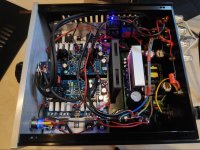
Hi all, I have been a HiFi enthusiast for very many years and have a great valve amp by Icon but during lockdown I thought I'd have a go at building at least one amp - something I haven't done for decades. The first amp was based on TDA7293 chips and sounds great and extremely detailed. I've just wired the second based on LJM L20 modules and a 500W +/-55V soft switch PSU + 2 x 10mF caps and Alps pot - all in a small case. I think it sounds good but its hard to compare by the time you swap all the cables. It certainly runs cool. I first wired up the amps and PSU and the bare angle heatsinks got quite warm.
Hi all, I have been a HiFi enthusiast for very many years and have a great valve amp by Icon but during lockdown I thought I'd have a go at building at least one amp - something I haven't done for decades. The first amp was based on TDA7293 chips and sounds great and extremely detailed. I've just wired the second based on LJM L20 modules and a 500W +/-55V soft switch PSU + 2 x 10mF caps and Alps pot - all in a small case. I think it sounds good but its hard to compare by the time you swap all the cables. It certainly runs cool. I first wired up the amps and PSU and the bare angle heatsinks got quite warm.
Attachments
Hi everyone,
I just ordered the L20v10.
I know this thread is for version 9, but I think it's a good idea to continue with this thread.
I will compare it to the other one from LJM that I have, the L12.2. If I am based on the L12.2, I expect exemplary sound.
I just ordered the L20v10.
I know this thread is for version 9, but I think it's a good idea to continue with this thread.
I will compare it to the other one from LJM that I have, the L12.2. If I am based on the L12.2, I expect exemplary sound.
The bigger differences:
- L12-2 is CFP output and Sanken output devices.
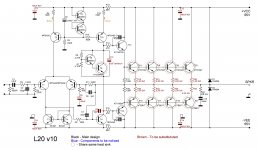
- L20-10 is Darlington output & generic D1047/B817 output devices.
Hi everyone,
I just ordered the L20v10.
I know this thread is for version 9, but I think it's a good idea to continue with this thread.
I will compare it to the other one from LJM that I have, the L12.2. If I am based on the L12.2, I expect exemplary sound.
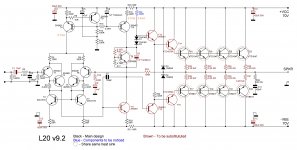
The only good thing in the V10 is the xVbe, all the rest is really bad compared to the V9.2, which is a "state of the art" design of asymmetrical - with feedback amplifiers. Both versions can work up to 140V.
Check both the schematics and you will notice that V10 has no more triplets in the output stage, the differential front-end is no more made out of Sziklai couples and degeneration resistors were omitted.
Do yourself a favor, see if you can change your order.
Attachments
Last edited:

The only good thing in the V10 is the xVbe, all the rest is really bad compared to the V9.2, which is a "state of the art" design of asymmetrical - with feedback amplifiers. Both versions can work up to 140V.
Check both the schematics and you will notice that V10 has no more triplets in the output stage, the differential front-end is no more made out of Sziklai couples and degeneration resistors were omitted.
Do yourself a favor, see if you can change your order.
Thanks, I just canceled the order.
Between version 9.2 and 9.3, is there an advantage?
I don't know any v9.3.
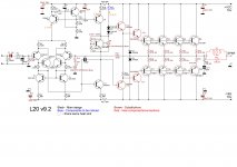
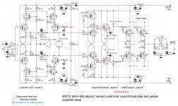
I suggest some mods to the V9.2, you see in the schematic. The mod on R16 has the purpose to have a lower bias, because I lowered all Re from 0.22 to 0.1Ohm. Never use a higher bias than the needed one (read D.Self), there is no pro, perhaps some cons.
You can ignore all transistors substitution, the originals are good. The L is 10 turns of awg14 on 1" diameter.
This will be one of the best diy-able amplifiers based on feedback.
140V-200W/8Ohm.
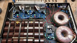
Take a look at mine. The heatsink is too small but for normal level listening, it's ok.
The two Ls were recalculated to have a smaller diameter.
I suggest some mods to the V9.2, you see in the schematic. The mod on R16 has the purpose to have a lower bias, because I lowered all Re from 0.22 to 0.1Ohm. Never use a higher bias than the needed one (read D.Self), there is no pro, perhaps some cons.
You can ignore all transistors substitution, the originals are good. The L is 10 turns of awg14 on 1" diameter.
This will be one of the best diy-able amplifiers based on feedback.
140V-200W/8Ohm.
Take a look at mine. The heatsink is too small but for normal level listening, it's ok.
The two Ls were recalculated to have a smaller diameter.
Attachments
Last edited:
Thanks Morigno for posting the diagrams. AS I mentioned before I used two V9.2 with a careful internal layout though had to tweak the bias current on one channel.
There seems little info on the distortion levels of V9.2 though very low ones are claimed for V10.
One thing that has always puzzled me is that audio amps seldom use multilayer circuit boards. In that they have much better properties regarding high frequency impedances and decoupling I though they would become standard for very high performance designs. Decades ago multilayer boards were incredibly expensive - but not so now. Another hangover from a past age?
Hi Marigno, I was wrong, I thought I saw a 9.3 version.
I will change the resistor R16 for a lower bias.
I have a question about the HP output filter consisting of the coil and resistor. This filter is not more necessary for loudspeakers with a difficult inductance like electrostatics or planar?
I will change the resistor R16 for a lower bias.
I have a question about the HP output filter consisting of the coil and resistor. This filter is not more necessary for loudspeakers with a difficult inductance like electrostatics or planar?
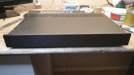
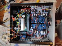
Hi Marigno - an interesting construction - I guess two power supplies? Ive attached the Mk1 version of mine again - Its a deeper box and by luck the slots in the case act as fins when the fan blows. I changed the fan to a quieter one that is fed all the time via a resistor so that it is even quieter. I found that the amp under normal conditions hardly changes temperature. I have a 50C thermostat on the power supply heatsink - that would switch on full fan power. This would not be audible at about 100dB in the room! A friend of mine wondered if a small inductor should be used on the output - maybe. I'll keep the output quiescent at 90mA as I'm not sure how the hfe of the output transistors drops off at very low currents. Certainly heat is not an issue. Jo
Attachments
Also another point - I notice there are no Base-Emitter resistors in V9.2 - see R17, R18 in V10. To add even 220R B-E resistors to V9.2 should be easy and not add too much dissipation to the drivers - though they are only 2W ! Perhaps 470R is better than nothing at HF.
Hi Marigno, I was wrong, I thought I saw a 9.3 version.
I will change the resistor R16 for a lower bias.
I have a question about the HP output filter consisting of the coil and resistor. This filter is not more necessary for loudspeakers with a difficult inductance like electrostatics or planar?
Do not change R16 unless you plan to lower all Re's to 0.1Ohm.
Putting on work an output filter is very easy so, in doubt, I did.
The poor L20 does not accomplish to drive my Acoustat 1+1 but drives well other traditional speakers, even if the power supply you see is greatly undersized (0.83x), it is not a double one, it is made out of 2 transformers 42V/100VA each, 200VA total for a total output power of 240W both channels, if you do't ask too much, the amplifier has a super-wide dynamic range.
But, if you use a 2x sized power supply, you should have no problem with any load.
Also another point - I notice there are no Base-Emitter resistors in V9.2 - see R17, R18 in V10. To add even 220R B-E resistors to V9.2 should be easy and not add too much dissipation to the drivers - though they are only 2W ! Perhaps 470R is better than nothing at HF.
I must answer by posting another scheme where you see how all is working in A-class except the final pair, working in NSCB.
If you want to improve significantly the triplet you should put a couple of resistors from the emitter of the drivers to the opposite power rail.
The schematic if about a diamond follower but the concept is the same, for the triplet you better use another couple of resistors with the pre-drivers.
But you need to better dissipate both the pre-drivers and the drivers. Try, it is worth! Perhaps with higher value resistors. Even a very high value (in order to not generate too much heath), prevents the transistors to switch off.
Attachments
The only good thing in the V10 is the xVbe, all the rest is really bad compared to the V9.2, which is a "state of the art" design of asymmetrical - with feedback amplifiers. Both versions can work up to 140V.
Check both the schematics and you will notice that V10 has no more triplets in the output stage, the differential front-end is no more made out of Sziklai couples and degeneration resistors were omitted.
Do yourself a favor, see if you can change your order.
IN V10, what does C6 do? its tied to the feedback loop, would it be by any chance audible?
- Home
- Amplifiers
- Solid State
- LJM L20 V9.0 Amplifier