You can connect a light bulb in series with 220 v.
It's easy.
As long as the light bulb is not very bright. The DC voltage of out GND is less than 50mV DC.
Listen to the sound again.
no problem. Remove the bulb.
If there's a problem, the bulb stays on. And it can avoid damaging transistors.
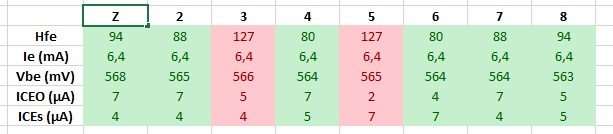
I have attached a table of my measurements that shows that the lower D1047 transistors are not biasing up properly. You can see that the currents (and base voltage) are very different between the two D1047. This is at idle with no input and no speakers. This is after one hour at idle with very very low +/- 25V suppliesMx50x2 bias voltage.
It can be measured. Voltage between d1047 B E.
Generally 530mv. We don't need to adjust it.
The bias through one D1047 is over 300% of the bias through the other D1047. 😱
What do you think is causing this problem? Very large mismatch between the two 649 drivers? Should I replace them? The base voltage is 16.4 mV higher on the D1047 with the much higher current.
I suspect this is related to why the other MX50x2 burned up.
By the way, the D1047 with the higher bias current gets much hotter than the other three when music is playing, even at pretty moderate volumes with +/- 25V supplies.
Attachments

Last edited:
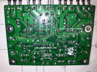
My outputs were matched ok, but the lower 649 drivers were way off (photo attached). That is in the one board that did not burn up.Here are some measurements on 8 D1047 I removed from my own MX50X2
2sc5200 were way closer in matching
It is a long story, but in the debugging process I found that one of the 0.22 Ohm resistors was a little high which was messing with my current measurements. All I had on-hand were 0.12 Ohm 3W Metal Film so I used those.
Also the 1N4004 diodes need to be matched and mine were way off. It turns out that the Vbe of the lower 649 drivers depends on:
1. The base connection to the bias device which is shared by both drivers. So that was not my problem.
2. The emitters of the two 649 drivers see a different voltage because they go through different 1N4004 diodes that connect to the output. So these diodes must be matched!
So I pulled the diodes and measured them: One measured 564 mV while the other 555 mV!
I measured almost half of my 1N4007 diodes before I found two that measured 603 mV and put those in. Then the bias currents were almost identical. 4.7 mV across one of the lower 0.12 Ohm resistors and 4.6 mV across the other.
In the end the 1N4004 diodes were the biggest problem producing 9 mV of the 16.4 mV offset in the Vbe of the two lower K1047/2SD1047 outputs. The remaining 7.4 mV was the mismatched 649 drivers and the high value "0.22 Ohm" resistor.
I am disappointed in the quality of these assembled boards. (The over 300% bias current mismatch in the lower outputs, the mismatched/poor quality transistors/diodes, shipping with fixed near zero bias current and the very messy soldering. The soldering is so messy I wonder if I was shipped a repaired/reworked board.)
I bought these assembled to save some time so that I could compare the sound of this design to the others (MA9S2 and the in-progress JLH and L7). In the future I think I will try to stick with DIY kits where I can measure and match all of the components, replace at least the big transistors and solder it properly.
The MA9S2 did not give me such troubles and that was a DIY kit where I measured every single component before soldering.
Now the real question is: Do I dare connect it to the full +/- 50V again? Perhaps with a light bulb in series with the transformer, small fuses and/or large power resistors in series with Vcc & Vee? And a large fire extinguisher?
Attachments
Last edited:
Distortion 0.3% by 50 W.
It would be great if someone with L7 experience could offer some advice on the L7 biasing (to make it adjustable).
Should we just replace the lower bias resistor with a 3296W trimmer?
Should we switch to an NPN transistor Vbe multiplier? Is that a good idea? Is that more thermally stable? Is that unnecessary?
Should we add source resistors (such as 0.22 Ohm)? Should we add gate stopper resistors? (47 Ohm? 220 Ohm? Less? None?)
Has anyone fully "figured out" and wrung out the L7?
Fake Irf 610?

The IRF 610 is marked "S". Could it be fake? The picture shows a S version. Maybe the bias transistor don't work as wished? Should I try to change them?
Have a nice weekend.
The IRF 610 is marked "S". Could it be fake? The picture shows a S version. Maybe the bias transistor don't work as wished? Should I try to change them?
Have a nice weekend.
I have found many fake transistors (Many MOSFET and also TIP35, TIP36, TIP41, 2SC5200, 2SA1943).
I would not be shocked if it was fake. In fact at the moment my assumption is that the power transistors in virtually all of these kits are fakes with the exception of D1047 and B817.
Did you solder it yourself? When I do that I put every single device into a little M328 transistor tester as a start. Now I am supplementing that with specific little test jigs for the power transistors. (And in general buying the power transistors and drivers separately at authorized distributors.) Every project built like that worked. On boards bought assembled (or using supplied power transistors in a kit) I have had too many headaches.
I also built LM358 controlled current sources/sinks on solderless breadboards where I can plug in transistors under test to load them at specific currents and voltages.
Last edited:
I have found many fake transistors (Many MOSFET and also TIP35, TIP36, TIP41, 2SC5200, 2SA1943).
I would not be shocked if it was fake.
Did you solder it yourself? When I do that I put every single device into a little M328 transistor tester as a start. Now I am supplementing that with specific little test jigs for the power transistors. (And in general buying the power transistors and drivers separately at authorized distributors.)
Should this still be necessary if the boards were ordered direct from LJMs Taobao store?
I don't know but I recommend it. I would hope not but I had a board burn up. I posted pictures of the LJM MX50x2 boards I bought and I asked if they were fake and for some reason I can't seem to get a reply. I assume they are genuine but I had problems and the soldering was very messy. (Pictures attached so you can see the soldering.)
So I don't know if they are genuine or not.
However I also found that the components (drivers and diodes for lower output transistors) were not matched on my LJM MX50x2. On my LJM L20.5 I found one board had nicely matched outputs and the other board did not.
I assume that these are genuine but one board burned up and I found unmatched components hence I found it necessary to disassemble, measure, match and replace.
So I would suggest that you measure and match all of the components. I suggest meticulous measurement and matching for power amplifiers as a rule of thumb. It is my belief that good quality and well matched components (outputs, drivers, biasing components) will pay off in terms of improved performance and reliability. To me it does not make sense to have unmatched or lower grade outputs or drivers in a high end amplifier. I also manually bias them with a trimmer.
Another poster measured the outputs in their MX50x2 and also found mismatched devices.
After meticulous measurement, matching and biasing I am find that both the MX50x2 and the L20.5 sound very good. I used TTC004, TTA004 and 2SC5200N in the MX50x2 (all genuine Toshiba bought from an authorized distributor). [I also needed new and matched 1N4007 diodes] I had to buy a larger number of transistors to allow for matching. However the TTC004 and TTA004 don't cost too much.
Attachments
Last edited:
Should this still be necessary if the boards were ordered direct from LJMs Taobao store?
From Another Seller at eBay. Wolf 6911
Bias
New IRF 610 for bias didn't change anything. Next step is changing the Mosfets. Gosh I am tired of fake products. Trump I wish you beat China more for the future.
New IRF 610 for bias didn't change anything. Next step is changing the Mosfets. Gosh I am tired of fake products. Trump I wish you beat China more for the future.
New IRF 610 for bias didn't change anything. Next step is changing the Mosfets. Gosh I am tired of fake products. Trump I wish you beat China more for the future.
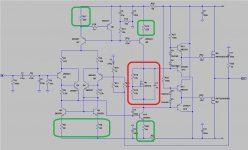
Did you first check for a suitable voltage drop across the resistors that I have circled in green? (Attached schematic.) That might help narrow down the problem. If there is current flowing through all of them and the IRF610 is good (and the two bias resistors) you should develop a bias voltage across the IRF610 that you can probe/measure in-circuit. If that is ok then I would guess that the totem pole gate drivers and output devices are next to probe/check.
I suggest doing that to make sure that there actually is current for the bias device. If there is what developed bias voltage are you measuring across the IRF610 as you adjust the trimmer?
And I assume you have already probed the resistors for the totem pole gate drivers, the resistors for the gates and the 4x diodes?
Attachments
Last edited:
I think I decided not to proceed with this. It's not worth it. 2 monos have been in use by a friend for years with no problems.
Last edited:
Hi friends, I recently bought a pair of L20.5 cards. I installed it in a large heat sink, with symmetrical 42vdc voltages. I'm having a problem with the temperature, it's overheating. I made a chain current in the branch, it's 220ma. Really very high, does anyone know where the resistor responsible for the polarization is (Bias)? I thank you immensely for any help.
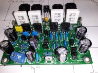
In the attached photo the low bias resistor is circled in RED with the large RED arrow.
If your bias is too high I suggest installing a larger 3296W multi-turn trimmer. For example, if your board has a 2.2k Ohm lower bias resistor and the bias is too high then I suggest installing a 5k 3296W multi-turn trimmer.
Solder the 3296W wiper to one of the ends of the trimmer to make a two terminal variable resistor that solders nicely in place of the 2.2k Ohm resistor. Before installed the trimmer set it to the maximum value and double check with an Ohm meter.
Before changing the bias look for the eight "sharing" resistors in the output that I have circled in light blue. Measure the voltage drop across all eight and make sure that the current is sharing (equally). I had an MX50X2 incinerate and I suspect it had very poor matching. [That is something that the factory should have taken care of.] I believe this because the other MX50X2 did not incinerate and I took it apart and measured the matching of all of the components and rebuilt the output stage with matched components.
By the way, I think you will like the L20.5. Mine sounds very nice.
Attachments

Last edited:
Hi Kazard,
my dear, thank you very much for your attention and respect for your colleague. I will definitely make the change. The resistor is 1kohm, amazed by the value so low, this explains the excessive polarization. A hug, best wishes.
my dear, thank you very much for your attention and respect for your colleague. I will definitely make the change. The resistor is 1kohm, amazed by the value so low, this explains the excessive polarization. A hug, best wishes.
If you have a 1k lower bias resistor then perhaps you should start with a 2k Ohm 3296W. Solder the wiper to one of the ends of the 3296W and set the 3296W to maximum resistance before soldering.
Then slowly adjust the bias upwards and keep readjusting until the amplifier fully warms up.
Then slowly adjust the bias upwards and keep readjusting until the amplifier fully warms up.

- Home
- Vendor's Bazaar
- LJM Audio