Re: Re: Could somebody ackbak this, pleeese?
Has this been clarified anywhere?
GM said:
These dims don't 'compute'.
GM
Has this been clarified anywhere?
Post #521
Hi Samuel Jayaraj,
I think so. This was in reference to the dimensions provided by sreamerusa in Post #491 for his Furybox. I indicated in Post #492 that there was something wrong, and GM stated more clearly in #497 that "These dims don't 'compute'." They don't.
Screamerusa has been updating his posting in:
http://www.screamersusa.com/furybox.html
but they don't look quite complete yet.
Until we get more complete dimensions there is no sense in trying to put this into AkAbak (I hope to find some time to draw around on this this weekend, but no promises.) .
Regards,
I haven't had a chance to recheck them.
I'm rather sure of the sqcm measurements, the length is hard to figure as the box is folded. I measured down the center line but I will recheck. The original path length I had was about 276cm.
Segment 1 and 2 are correct. the last segment should be correct.
Segment 3 is probably actually slightly longer, seg 4 is probably much longer as it includes the top, back, and 1/2 the bottom of the box to the center of the driver.
How should I remeasure the folded length?
Center, upper, lower, I.e. 3 measurements?
I will be adding another remeasure in CM.
Should I break it into small segments since my reflectors are not simple 45 degree angles?
Perhaps one of you could take the drawing and mark in red with a paint program, how I should divide the sections and I will remeasure accordingly. That would help a lot. The center of the driver is in a 4 sided taper so that will need to be 2 sections, the rest have parallel walls. (the cth was a 4 sided taper all the way through, ugggh!).
Sorry guys but I did kinda throw this together by feel and ear after over about 30 failures.
Last two assembled awaiting finishing.
Don't apologize - thanks for sharing all you have.
Do you have a slightly larger drawing? I'd be happy to mark it up for measurements.
Thanks again. I've been following this thread since it started, and have certainly learned some significant bits.
Do you have a slightly larger drawing? I'd be happy to mark it up for measurements.
Thanks again. I've been following this thread since it started, and have certainly learned some significant bits.
Thanks to everyone who is eager to take this further forward.
Yes, screamersusa, there is no need to apologise. You've done all you could in terms of both simulations and actual building. What's great is that you have roadworthy boxes and used them to the audiences' approval. Even 'if', I repeat 'if' the boxes don't correlate to simulations, but you've invariably got the crowd's approval for sound quality and 'feel', you've got something going.
This could and does lay the foundation for using an easily available driver like the 3015LF in a reasonably sized portable box, with FR between 40 and 125Hz.
Since, all of this development was taking a bit long and I still haven't got to learn too much of HornResponse (my other projects have been taking too much time, as always) I made 6 Nos. of double 15 ported boxes using 3015LF drivers. I'll try to post pictures soon. They were used in a few college fests from last month. They sound good. Folks around here are used to a more 'hard' sound than the 3015s produce but I like this driver - its bass performance is more tuneful and melodious.
Hence, I am still watching with interest because I am not averse to building something like the CTH or Fury.
Re: Post #521
Oops! Sorry about that, I missed your post since I'm not able to keep up with all the postings ATM on all the threads I'm involved with. All I did was read screamer's post and it wasn't a viable design as presented.
GM
tb46 said:I indicated in Post #492 that there was something wrong, and GM stated more clearly in #497 that "These dims don't 'compute'." They don't.
Oops! Sorry about that, I missed your post since I'm not able to keep up with all the postings ATM on all the threads I'm involved with. All I did was read screamer's post and it wasn't a viable design as presented.
GM
screamersusa said:How should I remeasure the folded length?
AFAIK the most technically correct way is to find/plot the acoustic center through the entire expansion, which isn't the center-line, but 0.707x the widest dimension as measured from the inside (shortest length) surface. AFAIK though, since this is so tedious/time consuming, folks not using Acad or similar just measure the inside and outside path-length and find its mean = SQRT(Ip*Op) since it's close enough and averages out such things as square corners, improperly angled corner reflectors, etc..
GM
Added another page
I added a "transfer page" to the furybox page.
Click the "Transfer page" text on the upper right.
There is a larger drawing, and the closest sims I could find on the first pass at re-engineering from the first actual build box.
Somewhere I have a paper plot of the original test box but it's probably worthless now anyway.
fb said:Sorry to double post this, but does anyone think it's worth my building?
It wouldn't be my first choice. FWIW, this one's smaller, doesn't need an inductor, has a wider usable BW without the need of a resonator, handles more power with a much better impulse response and should smooth right out with proper lining. The possible downside is that care must be taken in preserving its flare or its HF response could be severely compromised.
Anyway, gives you another design to fiddle with.......
GM
Attachments
FurySub_2009
Hi,
This is an attempt at drawing screamerusa's FurySub_2009.
I picked S3's location, because after that point the taper doesn't change, and before this point it does to some degree not matter in Hornresp (S2 to S3 areas and distance only, the actual convolutions are not modelled). The location of S2 and S1, as well as S4 and S5 are defined in Hornresp.
The area for S2 was picked on-axis with the horn, and by definition, in the middle of the speaker throat. As close as I can tell from the information provided S1 is a sharp corner between two side reflectors, I think Hornresp S1 minimum would apply there.
Still does not model too well.
Regards,
Attachments
How did you take measurements? I am in South Florida and I'd like to see how my modified Labs compare to your tapped horn.screamersusa said:The test cabinet had no bracing at all. 102-103db at 40hz.
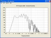
Thanks oliver for the drawing of scott's sub. I think I have a guesstimate why he has a winner. When he 'eliminated' the reflector at the upper front part of the cabinet, he said he got +3db at 100hz, vs with it. That 100hz is right in the 'valley' and would make this sub flat from 45hz on up, just like scott measured.
There must be a box resonance going on that hornresp isn't predicting, due to the folding, and scott 'stumbled' on a winner of a design. I know TD says you can't 'stumble' on these alignments, but I think scott got close.
My hat's off to you scott... you 'found' something by trial and testing, not by software.
Attachments
Posts #519 / #529
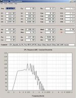
Hi fb,
Here is another take on building a tapped horn for the AV12H to your specs in Post #519. This one models well CON and EXP. Seeing the difference in response between screamerusa's measured results and the Hornresp model, I'd use OSB for a trial run. 🙂
Regards,
Hi fb,
Here is another take on building a tapped horn for the AV12H to your specs in Post #519. This one models well CON and EXP. Seeing the difference in response between screamerusa's measured results and the Hornresp model, I'd use OSB for a trial run. 🙂
Regards,
Attachments
TB46....wow that was quick. Thanks.
You pretty much nailed it. I added the angle changes to the first two reflectors.
I was looking at some fluid dynamics sims and remembering some basic room acoustic issues and applied that to how the reflectors were done.
While it was not built directly from a hornresp sim, all those failures with computer aided sims gave me the "Feel" to try winging it a couple of times. I'd say a controlled "stumble" would be pretty accurate.
Attachments

FurySub_2009
Hi screamerusa,
On your revision is that 12 degrees for both angle pieces, and is the opening 15x29cm? The resolution is just not quite good enough for me to read.
What do you think about jbell's suggestion (Post #532), that removing the internal reflector resulted in filling in the first response dip, and if so, have you tried removing the 'upper left hand' reflector (squaring the outside corner)?
It's definitely quite an achievement to get this close by modifying the enclosure "life".
Regards,
Attachments
Re: FurySub_2009
One side of each piece is cut at about a 12 degree angle, yes.
15x29cm is the original opening, correct.
I will do some rechecking in a couple of days as this is my bust part of the week. The drawing looks spot on.
Removing the other reflectors all yielded unacceptable dips and losses.
The one "missing" reflector was my insane atempt to "cut" the path length and create a higher spl "Bounce" affecting the 100hz area as I was not getting ANY gain over the direct radiator.
Please remember that the goal was not to build the best tapped horn live sub (That's Tom's job), but to match or exceed a double driver cabinet to eliminate the amount of amps and wall power required to achieve high quality high spl with a 2.6ohm minimum load (3 drivers).. Smooth response at about 102-103 db from 38-125hz would be a realistic goal, for a single
You should see the shocked looks from the "know it all's" around here when they find out I'm only pushing about 5,500 watts on the mains. Except for one moron who insists I HAVE to buy 4 of his double 18 JBLs, not one engineer or bs artist looking for a quick sale, has had anything but praise for the 4 subs I'm using.
That tells me we have something here that is worth refining.
Edit: Hmm. that's interesting. No the reduction was not intentional. Glad someone else noticed it. It does look like
some of the geometry could be altered a bit. to smooth out
the back angles without causing any problems.
tb46 said:On your revision is that 12 degrees for both angle pieces, and is the opening 15x29cm? The resolution is just not quite good enough for me to read.
One side of each piece is cut at about a 12 degree angle, yes.
15x29cm is the original opening, correct.
I will do some rechecking in a couple of days as this is my bust part of the week. The drawing looks spot on.
Removing the other reflectors all yielded unacceptable dips and losses.
The one "missing" reflector was my insane atempt to "cut" the path length and create a higher spl "Bounce" affecting the 100hz area as I was not getting ANY gain over the direct radiator.
Please remember that the goal was not to build the best tapped horn live sub (That's Tom's job), but to match or exceed a double driver cabinet to eliminate the amount of amps and wall power required to achieve high quality high spl with a 2.6ohm minimum load (3 drivers).. Smooth response at about 102-103 db from 38-125hz would be a realistic goal, for a single
You should see the shocked looks from the "know it all's" around here when they find out I'm only pushing about 5,500 watts on the mains. Except for one moron who insists I HAVE to buy 4 of his double 18 JBLs, not one engineer or bs artist looking for a quick sale, has had anything but praise for the 4 subs I'm using.
That tells me we have something here that is worth refining.
Edit: Hmm. that's interesting. No the reduction was not intentional. Glad someone else noticed it. It does look like
some of the geometry could be altered a bit. to smooth out
the back angles without causing any problems.
I think figuring out what made the core section work is probably the key to improving the whole cab.
3 questions, that I don't think we have, or can easily get answers to:
1. why does the angled part from s1 to s2 matter so much? hornresp doesn't show appreciable change with modifications to this part of the horn.
2. Why does removing the one reflector add +3db at 100hz? hornresp doesn't have any way to model with or without it.
3. Why does a solid rear brace diminish output down low (40-50hz, I'm guessing)
It would appear that there are MANY more acoustic interactions happening, than what geddes would call: "lumped masses"
Somehow, what I 'thought' I knew about TH, seems to be slipping away from me, and I'm realizing just how much I don't know about these beasts.
- Home
- Loudspeakers
- Subwoofers
- Live sound specific Tapped Horn thread...