
I thought I don't need this, yet it took a day to arrive on my own ZM project list. Darn SissySIT propulsing it!what's not to love ........
now, all of nice cozy days and nights, Holidays with all Family creatures together, I had some lazy fun
as I'm not having more than enough already on list to finish, there is one more
(as always, it'll be either All The Glory, or Major Public Disgrace ....... nothing in between )
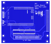
Show us more!! What does the logic board look like?

of course!Can I use ZM logo on my motorbike? 😆
but - only if it's 'Talian!
similar to one in Iron Pumpkin, shown on my ootoobe vids, with few changes - need to include few itsybitsies to enable proper stndby operation ...... meaning killing da TF screen while killing amp's main(s) DonutI thought I don't need this, yet it took a day to arrive on my own ZM project list. Darn SissySIT propulsing it!
Show us more!! What does the logic board look like?
still thing to be done, but trivial; I know that schm/pcb itself will be done in one evening, but code will ask for more time
anyway , nice and lazy project, never thought that I'll ever mess with integrated amp, and all remote/lazy but bells and whistles ...... but it seems Pa spoiled me to the (my very Omnienormous) core

as always, experience is confirmed again - auxiliary circuits are more problematic than audio (at least for me.......... helped with fact that I have crappy criteria for my audio constructions )
problem with TFT displays - as with anything - choice dictated with price ( not so much), performance (oh yes), availability (oh yes) ...... but not many of them are having solved/presented manipulation of LED backlight levels and state
and it is logical to organize things that display/light is gone Dodo when amp is sleeping
anyway, TFT display used for IP is perfect ........ but you can't kill neither 5V nor GND, from various Logic architecture reasons .......
ok, let's go backwards ........ I don't care for display actually being On all the time , nor for arduino ; Arduino must work in stand by of amp, display itself is not problematic neither from power consumption nor from longevity reasons....... what is important is just that damn light ..... so - obvious hidden solution is - kill just LED
that means - desolder 2R2 SMD on display pcb, it's in line from 3V3 reg to LED anodes
put 2 wires from resistor pads, route them to high side mosfet switch on arduino board and control damn thing
did I drew first iteration with low side switch , killing GND for display ......... just to check later and realize it's no-no solution in Arduino world ..............
life is fun .........
)problem with TFT displays - as with anything - choice dictated with price ( not so much), performance (oh yes), availability (oh yes) ...... but not many of them are having solved/presented manipulation of LED backlight levels and state
and it is logical to organize things that display/light is gone Dodo when amp is sleeping
anyway, TFT display used for IP is perfect ........ but you can't kill neither 5V nor GND, from various Logic architecture reasons .......
ok, let's go backwards ........ I don't care for display actually being On all the time , nor for arduino ; Arduino must work in stand by of amp, display itself is not problematic neither from power consumption nor from longevity reasons....... what is important is just that damn light ..... so - obvious hidden solution is - kill just LED
that means - desolder 2R2 SMD on display pcb, it's in line from 3V3 reg to LED anodes
put 2 wires from resistor pads, route them to high side mosfet switch on arduino board and control damn thing
did I drew first iteration with low side switch , killing GND for display ......... just to check later and realize it's no-no solution in Arduino world ..............
life is fun .........
Attachments
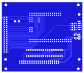
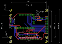
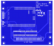
illustration of ZM's laziness
it was easier drawing two iterations of same module than going to workshop and check situation with display as is.......
first one with low side switch (ok, intended too kill entire display, no clever/Iznogood), then rummaging through internet - seeing majority of displays having convenient series resistor for LED on plus side
no such info for exact display I'm using, of course .......
so, I made iteration with LED switch on high side , and only after that I actually did go to Workshop, to check my display....
guess what - 2R series resistor is between LED cathode and GND ......... so low side switch is what I need
check was successful, 2R removed, two wires, 2R inline with mAmeter ......... off and on is working (when On-LEDs sucking 95mA), while display itself is happily undisturbed working all the time, with or without light
Now you see me, now you Don't!
and I can use no brain ( desirable state of affairs), resorting to TO220 BUZ11, instead of SO8 critter, as in previous case
Attachments

That's a neat package there, very tidy! I did not know of your YouTube endeavors😉 are you writing the code for multiple size displays? I saw you worked with a smaller one earlier on in development.

Man, Seeing those fancy displays is gonna push me past the tipping point for a Pumpkin SE. ZM, are logic boards and screens an available upgrade for kits at this time?
entire main Shebang (MoBo with AVC module) with control arrangement of choice :
-two mechanical rotary switches for front plate, or
-Logic module with TFT and encoder for front plate.... and fancy remote for Sofa
-two mechanical rotary switches for front plate, or
-Logic module with TFT and encoder for front plate.... and fancy remote for Sofa
You ought to prescribe a ‘standard’ modu chassis, then you could offer entire manufactured front plate. Engraved ZM logo with pretty infill, maybe even a nice orange anodization… 😀
that would be too much efforts from my side
yup, prescribed is Slim Line 3U/280 or 3U/350, preferably Fe covers
I have all files for milling and drilling both back and front plate
working slowly on my own CNC (damn, where is my Gemini when I need him), so maybe then
now, really can't cope with all ideas
yup, prescribed is Slim Line 3U/280 or 3U/350, preferably Fe covers
I have all files for milling and drilling both back and front plate
working slowly on my own CNC (damn, where is my Gemini when I need him), so maybe then
now, really can't cope with all ideas
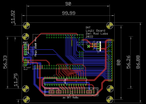
the
font is very nice.something as this (it'll be updated soon with actual iteration of IP)
That sounds like more than enough for us greenhorns to get a nice pumpkin together 🙂that would be too much efforts from my side
yup, prescribed is Slim Line 3U/280 or 3U/350, preferably Fe covers
I have all files for milling and drilling both back and front plate
working slowly on my own CNC (damn, where is my Gemini when I need him), so maybe then
now, really can't cope with all ideas
Fonts;
First one is font made of Nikola Tesla's handwriting (web origin), second one is Gradl Regular
both of these I needed to convert to Arduino applicable fonts
personally, idea of using these two fonts was main reason to pursue TFT option, and I'm happy with outcome, even if I spent numerous hours solving all issues with software I was just learning, and with hardware (TFT displays in general) having, mildly put, dubious technical knowledge base
at least I had problems, my brain functioning mostly on intuitive basis, while I'm finding most of software opposite to my intuition; well , world functions that way nowadays and that's how my brain is ... opposite to everything
but, I did learn with years to not even question enormity of my stubbornness (boy, how many double ones in one word?)
in any case, whenever I'm in trouble, this is most proper tactical approach:
Attachments


I have been trying to find someone who make small metal plaques for the front of my ZM amps using Tesla fontCan I have the sofa without the remote, oh Mighty? 🤪
Very nice the idea of Tesla calligraphy
something like
Zen Mod Labs
Old Soul
Zen Mod Labs
SissySIT
No luck so far
- Home
- Amplifiers
- Pass Labs
- List of ZM projects