Then the coils are fine. You could use the 47 µH version. It can take 130 mA.
Part number is ELJFB470□F.
Anyway, there is enough choice in 1812 SMD size also 200 mA versions from Coilcraft.
Part number is ELJFB470□F.
Anyway, there is enough choice in 1812 SMD size also 200 mA versions from Coilcraft.
Last edited:
So now I only need to figure out how to properly route the buffer itself and then merge the two PCBs.
BTW, thanks for the invitation to the non modular PCB design committee.
Let's see if I'll fit the requirements with my design🙂
Thanks all of you guys for help! It is really appreciated.
I hope I'll succeed with your guidance.
Oleg
BTW, thanks for the invitation to the non modular PCB design committee.
Let's see if I'll fit the requirements with my design🙂
Thanks all of you guys for help! It is really appreciated.
I hope I'll succeed with your guidance.
Oleg

Because I split the left and right channel returns once they leave the source and I do not want them to meat again. It helps to eliminate the unnecessary ground loops if separate RCA cables are used for left and right channels.
Oleg
Oleg

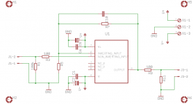
I have finally dropped the idea of extra gain and stopped at a unity gain buffer configuration. It simplified the matter a lot. Now I can use a complete ground plane. The new (and I hope the final) version of the buffer PCB is attached.
Please comment!
Regards,
Oleg
Please comment!
Regards,
Oleg
Attachments

@OlegSh:
So ... did some tests to conclude that an IC buffer exceeds based on discrete components?
I really want an amplifier or headphones, but this doubt is killing me. 😛
So ... did some tests to conclude that an IC buffer exceeds based on discrete components?
I really want an amplifier or headphones, but this doubt is killing me. 😛
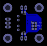
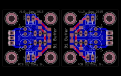
No, I did not. That is why I'm trying to complete my project. I also have designed a small B1 buffer PCB (attached) which can be used with the PSU shown in above posts but I doubt that my listening tests (assuming that all works at all) will be conclusive... but who knows!? So I have same problem as you.
Attachments
I have a practical question regarding op-amp supply voltage. LME49990 has +-18VDC max supply voltage. To be on a safe side should I aim for +-15 VDC ? What is the common practice in this regard?
Thanks,
Oleg
Thanks,
Oleg
Hi Oleg,
Heat is the enemy of all things, semiconductors are sensitive to heat. If you don't need to run at 18V, then don't. 15 VDC is reasonable, but if everything else is running from 5 VDC rails you could even drop it to 10 VDC without losing performance. Check the data sheet for the LME49990 to see where the performance starts to drop off and hang just above that point as long as your signal will not get close to your supplies.
-Chris
Thanks a lot Chris,
If I understood the datasheet right, the LME49990 does not show performance degradation regardless of supply voltage. So I'll probably aim at 10~12VDC, thus same supply settings will also suit B1 buffer should I decide to experiment.
Regards,
Oleg
If I understood the datasheet right, the LME49990 does not show performance degradation regardless of supply voltage. So I'll probably aim at 10~12VDC, thus same supply settings will also suit B1 buffer should I decide to experiment.
Regards,
Oleg
Hi Oleg,
Thanks.
What I'm trying to show is that most of the answers are common sense things. That is of course, when you can break the question down to ask those questions.
-Chris
Thanks.
What I'm trying to show is that most of the answers are common sense things. That is of course, when you can break the question down to ask those questions.
-Chris
Most of questions that I ask are because of the lack of experience. I can pretty well understand the datasheet info and also suggestions/advises given here on the forum. But the true art is in the correct handling of exceptions by making the right compromises and here only experience can help which I don't have. So you guys are really helpful by sharing your knowledge.
Regards,
Oleg
Regards,
Oleg
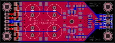
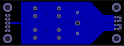
Just Married!
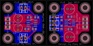
After a lot of doubts I have finally combined the PSU and the buffer together. I really like what it looks like now but it is mostly from aesthetic point of view🙂 I have no idea what kind of performance to expect from this combination but soon I'll have a chance to try it.
If someone sees obvious mistakes/problems with the PCB please let me know.
Regards,
Oleg
Attachments
- Status
- Not open for further replies.
- Home
- Source & Line
- Analog Line Level
- Line level buffer: discrete or ICs based?