Thanks Jon. This manual only appears to show the power amp for the HD100, not the 112 (unless I'm blind)? I'm looking for supply voltages for troubleshooting a 112 I recently acquired.
Not sure yet. I'm in the early stages of troubleshooting a SV112 in unknown working condition (using this excellent guide) and wanted to see what voltages I should expect on the output of the power transformer (as well as on the power supply board). I am getting a brightly lit bulb on my dim bulb tester with tubes+speaker attached. Removing the tubes and speaker caused the DBT to stay dim, but I began smelling some electronics so I shut everything down.
To make matters more complicated, this amp has been modded with the SVpre board by Strymon. This mod is on the preamp side, so I don't believe it is causing the bright DBT.
I should probably start a new thread in the troubleshooting section...
To make matters more complicated, this amp has been modded with the SVpre board by Strymon. This mod is on the preamp side, so I don't believe it is causing the bright DBT.
I should probably start a new thread in the troubleshooting section...
Power transformer secondary voltages look good, as well as the preamp tubes. However, when I plug the power amp tubes back in (and reconnect the speaker), the DBT glows brightly. Any other tests I should run before swapping to a new set of power tubes? Looks like I can get a new matched pair for ~$50 shipped on Amazon.
I should also mention: I'm using a 60W bulb in my DBT, but it is certainly glowing brighter than I would expect for this 40W amp at idle.
I should also mention: I'm using a 60W bulb in my DBT, but it is certainly glowing brighter than I would expect for this 40W amp at idle.
Last edited:
It seems to be a fixed bias amp. There are two test points, TP_-biasV6, TP_-biasV6 on page 9. I am guessing a voltage of -35 to -40V would be a starting point to bias the tubes. Check that without the tubes in. If it is lower adjust the pots.
while a DBT is useful it can't tell at what frequency current draw is taking place.
the DSP in these can pull down a few amps on their own so that should be accounted for.
what is the listed current draw on the amp?
the DSP in these can pull down a few amps on their own so that should be accounted for.
what is the listed current draw on the amp?
Should I adjust this before ordering new tubes? Is it possible the bias is causing the bright DBT?
ensuring bias is ballpark as per Printer2's advise is good, excessive draw because of improper settings is a possibility. don't jump to conclusions without verifying things
Hmm, I seem to be reading 0.0 mVDC at the bias test points when the amp is powered on (standby on) and power tubes + speaker are removed. Same reading when power tubes and speaker are connected. Guess I'll check the bias supply circuit next. I did measure 60VAC at the PT secondary when it was disconnected; perhaps a cap or resistor shorted?
Yes, all fuses are good.
I have a few 6L6s lying around that aren't matched, would it be ok to swap in 2x of these unmatched tubes quickly and see if the DBT stays lit?
I have a few 6L6s lying around that aren't matched, would it be ok to swap in 2x of these unmatched tubes quickly and see if the DBT stays lit?
Last edited:
Did some checking in the bias supply circuit. A bit of guesswork involved, but the SV100 bias supply SCH seems very similar to my SV112 Mk1.
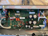
I traced the 60VAC input from the PT secondary header to the bias adjustment trimpots, see first photo. I then measured the resistance from the bias test points (TP_BIASV4 and TP_BIASV3, which should be pin 2 of the trimpots) on the bias header to the leg of R54 (R84 on the SV100 SCH, which should be pin 1 of the trimpots).
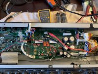
I was reading the full value of the trimpots (~20k each) regardless of trimpot adjustment. I sprayed contact cleaner on the trimpots, but that didn't change anything. This resistance (shown in the second picture) should change as I adjust the trimpots, correct?
Is it worth removing the trimpots from the circuit and ensuring they operate correctly?
I traced the 60VAC input from the PT secondary header to the bias adjustment trimpots, see first photo. I then measured the resistance from the bias test points (TP_BIASV4 and TP_BIASV3, which should be pin 2 of the trimpots) on the bias header to the leg of R54 (R84 on the SV100 SCH, which should be pin 1 of the trimpots).
I was reading the full value of the trimpots (~20k each) regardless of trimpot adjustment. I sprayed contact cleaner on the trimpots, but that didn't change anything. This resistance (shown in the second picture) should change as I adjust the trimpots, correct?
Is it worth removing the trimpots from the circuit and ensuring they operate correctly?
Attachments
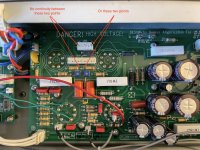
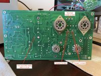
I removed the power board and took a few more measurements, see below. Nothing is obviously damaged (no crispy bits or missing solder).
- The bias test header pins measure only a few ohms between them, is this expected?
- The trimpot measurements are all over the place; I'll remove them from the circuit next and retest
- C56 measures very high (~86uf instead of 22uf) in circuit. I'll remove it from the circuit and check it as well.
- Still no continuity between any of the header pins and any of the trimpot legs
Attachments
- Home
- Live Sound
- Instruments and Amps
- Line 6 Spider Valve 112 Schematic