Line 6 is distributed by Yamaha. If you know a local Yamaha approved service agent, they will be able to download the service data for you from the Yamaha JP website. Sorry, they took my password years ago.
Trimpots and 22uf capacitor measured ok out of system. A little lost as to what to try next, any suggestions?
Reflowing the joints in this area didn't help. I don't see traces coming from the 220k resistors to the bias test header, but there must be some according to the SCH, right?
The bias test points go to One Ohm Cathode Resistors, NOT the grid voltage.
With tubes out the test points will read zero.
Yes, you do want to check grid voltage *before* you put tubes in. Measure at the 220k resistors' legs.
With tubes out the test points will read zero.
Yes, you do want to check grid voltage *before* you put tubes in. Measure at the 220k resistors' legs.
Attachments
Last edited:
Thanks PRR. I measured ~-33VDC and ~-35VDC at the 220k resistor's legs with no power tubes (preamp tubes were installed and standby+power switches were "on"). This looks about right for a class AB amp with 6L6GCs, right?
Last edited:
Hm, Question.
What's the problem with the amp?
No sound?
Output tubes glowing red?
Distorted sound?
What are the symptoms you get and do seems abnormal?
Or is it just being curious with a broken amp at the end of the quest?
What's the problem with the amp?
No sound?
Output tubes glowing red?
Distorted sound?
What are the symptoms you get and do seems abnormal?
Or is it just being curious with a broken amp at the end of the quest?
The amp has test points for the bias voltage ans test points to measure the bias current. I was hoping to get a measurement of the actual bias voltage, seems it was 33V. I thought if it was not in the right range the tubes might have been red plating causing a bright bulb condition. Sorry for the confusion.
I haven't gotten to the point of testing audio yet. Here are the odd symptoms that I'm encountering:
My next step was going to be installing a new set of 6L6WGCs; is there anything else I should test before this?
- Bulb in DBT glows bright when power tubes are installed and amp is powered up. I'm using a 40W bulb, maybe I should be using a higher wattage for this amp? DBT is dim with power tubes removed.
- No matter how I turn the bias trimpots, I only measure ~15mVDC max at the bias test header.
- LCD screen shows black bars. Searching around online, this seems to be a common problem with the DSP board on these amps, but I'll focus on this once I have the bias sorted out.
My next step was going to be installing a new set of 6L6WGCs; is there anything else I should test before this?
I have a few 6L6GCs (not 6L6WGCs) lying around that I think are still good; can I swap them in quickly and see if the bias or DBT behavior changes? The new tubes wouldn't be matched, but I can't imagine a quick swap would cause any harm, right?
Swapped in a different set of 6L6s; no change in behavior. I did notice that the heater voltage drops to about 3.3VAC across pins 3 and 7 of the power tube sockets once power tubes are installed (~5.5 VAC without tubes installed). Is this expected?
your not doing hot swaps are you? do you have a load connected?
and just how long are you running it? keep in mind that until the heaters come up to temperature your dbt will glow brightly.
and finally you should not be attempting bias or any voltage reading while on the DBT your incoming voltage will be low. a DBT is is a fail safe for hard shorts.if you have a second meter available monitor the incoming voltage(use some clip leads to safely connect this meter) to get a better idea just where the ac level is at.
Not doing hot swaps (powering down before swapping tubes). I am using a speaker whenever the power tubes are installed.
I've let it run for ~2-3 minutes while monitoring heater voltage, should I wait longer?
I've let it run for ~2-3 minutes while monitoring heater voltage, should I wait longer?
I measure about 96VAC on the primary side of the PT with the DBT attached and no power tubes installed (amp in standby).
Attaching the power tubes and speaker (after installing with power off) drops the input to ~75 VAC in standby mode (voltage starts lower and slowly increases to this value). Switching the standby switch to "on" drops the input to ~50 VAC, which explains the low bias number.
Should I remove the DBT and check bias? The bright DBT makes me nervous; is there any other test I should check to make sure I don't damage anything without the DBT?
I also noticed that the LCD screen has the black bars when the amp is in standby, but the screen turns off when I flip the standby switch to "on". Looks like I have some problems with the main board as well...
if it has behaving that way on a100w lamp i'd be nervous but you said you where running a 60 and at one point a 40 w lamp....point being the wattage of the limit lamp will vary the ac based on current draw.
have you looked and the UL info for voltage and current rating on the amp?
the digital portion of this amp is not going to be happy with voltage and current starved conditions.
going from standby to operate is going to draw a pulse of current and depending on just what the circuit is that inrush is crashing the lcd and processor not to mention the low voltage regulators.
if the fuses are all correct ratings and types you should be safe to come off the DBT just be observant and don't leap into testing right away....
Thanks turk. I powered up without the DBT in series (with speaker and original power tubes connected). After ~10 minutes of monitoring without smoke or smells, I checked the heater voltages: they looked good (~6.7 VAC).
Next, I flipped the standby switch on and set bias: I was able to adjust both tubes to ~35 mv DC without too much trouble.
LCD screen showed bars in both standby and "on" states. Next step is to check voltages on main board; see picture for PCB in question. Unfortunately, a lot of these ribbon cables are glued on...
Attachments
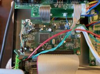
Probing around in the main PCB I found that I'm only reading ~+1.9VDC at the positive of C80 (should be +3.3VDC) here. +12VDC, -12VDC, +8VDC, and -5VDC rails look ok. However, I do read ~+5VDC at one side of C6, so it looks like there's something off in the U3/C80 area.
Any other easy ways to check if U3 is ok? Would a bad C80 cause this low voltage reading?
Any other easy ways to check if U3 is ok? Would a bad C80 cause this low voltage reading?

because there's little chance of a full schematic googling the processor board trouble shows that the problems stem from inadequate heat sinking of the regulators causing the voltage to collapse and the processor itself running hot and there are several YouTube vid's showing some homebrew heat sinking mods(a few scared me) but most worked.
- Home
- Live Sound
- Instruments and Amps
- Line 6 Spider Valve 112 Schematic