take a break it's too close to Christmas...have a scotch with me if nothing but in spirit i wish you well...
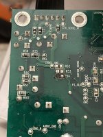
Replaced R53 and R54 (and U3 while I was at it). Unfortunately, powering back on recooked R54. The 5V rail was ok when I checked it before, what else could be causing too much current to flow through R54? Maybe a bad U13? Should I remove R54 and recheck the 5V rail? See second picture below for relevant area of schematic; see post #2 for full schematic.
Attachments

All the electrolytics LOOK ok, but I don't have an ESR meter to check them. Is there anything else I can do to evaluate if they are still good? Should I just replace them all?
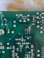
Removed and checked C20. Capacitance reading was ok, but resistance values were a bit wonky so I replaced it. Replaced the cooked R54 as well.
Is there a smarter way to power up this board to see if I have an issue, or is it more a flip-and-pray process?
Is there a smarter way to power up this board to see if I have an issue, or is it more a flip-and-pray process?
Replacing C20 did the trick! The amp works fine now. It even survived me running it for a few minutes with the speaker cable not fully plugged in (whoops!).
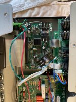
I also added some heatsinks on the voltage regulators and DSP chip to help ease the overheating issues common to these amps.
Thanks all for your help, and happy new year!
I also added some heatsinks on the voltage regulators and DSP chip to help ease the overheating issues common to these amps.
Thanks all for your help, and happy new year!
Attachments
Just found this thread - helping a friend troubleshoot his SV 212.
For those interested, a Rumble video from Electronic Investigation shows the troubleshooting/repair of this problem.
https://rumble.com/vl36fe-line-6-spider-valve-112-troubleshooting-and-repair-ep-003.html?start=875
Starts at the point of diagnosis and repair, but feel free to view all for the troubleshooting plot with all the suspense and intrigue. 😉
- Home
- Live Sound
- Instruments and Amps
- Line 6 Spider Valve 112 Schematic