Doesn't matter. If ldrs are well matched you will keep channel balance. What changes is the volume curve which might or might not be perfect even if both were exactly 100k.
Channel accuracy of the Dual 100kohm log pot is not important, what is important is that you use a 100kohm log dual pot and it is wired as per the circuit diagram.
Cheers George
Cheers George
Just received my 32SR2(Sorted) delivery yesterday and did a quick match within +/- 0.5 ohm at 2mA. Unfortunately my el-cheapo diode tester doesn't go any lower than that. Of the 25 received I got three quads, two triples, three pairs and one oddball. They were all of the same batch (A) and all were close to 40 ohms at 2mA so should be well below that at 20mA.
GeorgeHiFi, thank you for this. I started to design a passive preamp years ago and gave up due to the rubbish parts available. I can finally dig that chassis out and fill it with goodies. I'll probably use a 78L05 since it will handle 100mA easily and I don't plan to add anything else to it.
One thought: it may be possible to cancel much of the temperature drift by using a thermistor instead of the 100 ohm resistors. I didn't read the whole thread - hey life's too short! - but in scanning every 10th post or so I didn't see anyone mention that possibility. Then again the value is too small, isn't it.
Last edited:
haiqu let us know how it sounds when you finished.
And temperature drift isn't an issue, if you don't have the transformer in the same chassis, you'll be OK.
Cheers George
And temperature drift isn't an issue, if you don't have the transformer in the same chassis, you'll be OK.
Cheers George
I think the most important thing the lightspeed accomplishes is that it still maintains lots of detail, energy and vibrancy even at very low volume levels which is not possible with traditional ways.
Last edited:
I think the most important thing the lightspeed accomplishes is that it still maintains lots of detail, energy and vibrancy even at very low volume levels which is not possible with traditional ways.
Yes it keeps the body to the music, unlike others than seem to go thin in the mids when turned down.
It "may" have something to do with the the small amount of 2HD Cadmium Sulphide cells have, a bit like tubes.
Or because there's "no contacts in the signal path" (wiper of volume controls or input switches).
Or it's a combination of both, a little 2HD and no contacts in the signal path.
Something to think about:
The volume potentiomer is the most questionable/unreliable part in any preamp, they all sound different, even though they are the same value. They start to deteriorate from the first rotation.
What you have in them is a very light contact metallic wiper on a carbon, or conductive plastic resistance track. EE laws tell you that current passing through two dissimilar materials that are a light touch contact, such as the wiper on the resistance track in a pot, is not a good thing, and that, that point of contact can have a diode effect. (ac music signal with a diode effect in the path? isn't that rectification in a small way?)
Cheers George
Last edited:
Also here something to ponder over, from (I bows me's head) my God!
https://www.stereophile.com/images/119gdreams.distortiongenerator.jpg
Kent English raised his hand: "Why would we want to add distortion?"
Pass smirked. "Because this is entertainment, not dialysis! . . . and I am giving these things away!"
Pass reminded everyone that "The H2 works best with simple material. With complex material, second harmonic may be more of a burden than an asset. When you turn the knob to the left, which is negative-phase second harmonic, the room gets bigger, more atmospheric, you start to see images of musicians. Turn the knob right, you get positive-phase second harmonic, which brings the musicians closer to you: drier but more intimate, more apparent detail. But of course," Pass reminded us, grinning hugely," this is all illusion!"
Cheers George
I recall that the Lightspeed has a fair dose of 2nd....

Hey Papa how ya been mate, nothing get Pass'd🙄 you.
It can give up to .1% with 2v in
Cheers George
Attachments
Last edited:
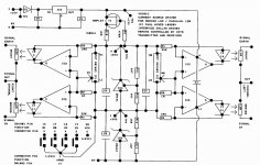
Sorry to interrupt this thread with an old subject. Does anyone have a diagram showing how Paul's VCCS light speed board connections are used? I see the input and output, but fail to understand how the plugged in terminals and test points are used.
Connections 1-6
1 (14) AGND
2 (16) Balance Left
3 (17) Balance Right
4 (18) Volume Down
5 (19) Volume Up
6 (20) Vcc
where the numbers in brackets are the corresponding pin numbers for the DS1802.
Test points TP1-4
* TP1 +15V
* TP2 +12V
* TP3 +8V3
* TP4 +3V3
See:
https://www.diyaudio.com/forums/analog-line-level/80194-lightspeed-attenuator-passive-preamp-108.html#post1825228
Attachments
Last edited:
Putting four momentary switches between pins 2,3,4,5 and pin 1 will operate the functions.
Last edited:
Thanks cyteen, I was looking through my unfinished projects and discovered three main boards, so I am scratching my head trying to remember what I wanted to do with these. A quick search showed three different PCBs would be a set, so it further confuses me.
Now I am wondering whether I can get something to make a few sets and trying it out.
Now I am wondering whether I can get something to make a few sets and trying it out.
If you have three you could cascade them via each DS1802 pin2 to pin4 of the next chip.
There is also an arduino library for the DS1802 3-wire interface so adding a remote other than the extra boards from Paul Hynes wouldn't be difficult.
ArduinoLibraries DS1802
There is also an arduino library for the DS1802 3-wire interface so adding a remote other than the extra boards from Paul Hynes wouldn't be difficult.
ArduinoLibraries DS1802
Hello everyone, first of all a big thank you to George who allowed me to get to know a little big preamplifier.
Now that I heard it play I would like to put a remote controlled potentiometer and more inputs and bought the kit MV04Google Image Result for https://ae01.alicdn.com/kf/HTB1m4yshtfJ8KJjy0Feq6xKEXXa1/MV04-Quadrupla-ALPS-Motorizzato-Telecomando-Potenziometro-di-Ingresso-9-12-V-AC.jpg.
Unfortunately I'm not great at electronics and I don't understand how to connect the wires of the old double potentiometer to the new kit.
Has anyone done it yet and can you help me?
Thank you
How does the LDR attenuation method compare to volume control ICs? Also, is it possible to drive the Ldr from an mcu using filtered pwm signal or dac?
I built a point to point LA some years ago which has performed faultlessly. I haven't used it for about a year due to using other DIY stuff. I have now had a re-jig/tidy-up of my system and put the LA in. For some inexplicable reason I seem to have much less control over the volume. It gets loud very quickly which it didn't do before. Do these things go off? Is it likely to an LDR or PS issue? I am using exactly the same PS as previously.
- Home
- Source & Line
- Analog Line Level
- Lightspeed Attenuator a new passive preamp

