Gootee,
can you convert the seconds of pot rotation to attenuation for me?
eg. at 12seconds, what is the attenuation?
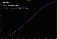
It would be easier to just plot the attenuation. I'll post the plot when the simulation finishes.
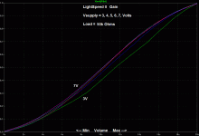
EDIT: I plotted the GAIN, instead (attached).
Attachments
Last edited:
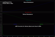
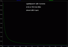
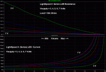
Just for fun, I also plotted the LDR resistances and the LED currents.
I included magnified views of the two areas of the shunt LDR's current, so the values could be read more easily.
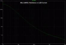
Edit: I added a plot of the NSL-32SR2S model's resistance vs current. You can see a couple of minor bumps where I apparently was slightly off when I measured the plot from the Silonex website.
Attachments
Last edited:
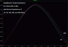
I took a crack at plotting the output impedance, for source impedances of .01, 50, 100, 200, and 400 Ohms. I put a resistor across each input for the source impedances and placed a DC current source from ground to each output. Load resistances were removed (opened). As the pot was varied linearly from min to max, I plotted one output voltage divided by its current source's current. The source resistances were stepped to the values in the list, for the plotted runs.
Attachments
WOW!!!
Thanks for posting that Tom as it's way better than I measured 5 years ago, I must have had a DMM that was out of calibration, this result shows that it's no worse than the output impedance of most tube preamps. I knew it remained stable in the MKII version but had no idea that it was this low which is great, better change my sales pitch.
Cheers George
Last edited:
The attenuation vs rotation looks very similar to a lin vol pot with log faking resistor.
I am surprised at how little the volume/attenuation changes in the second half of rotation.
I also draw attention to how much of the volume control is using the very low LED current range from 15uA to 200uA.
The LED current >500uA is rarely required for normal system gain, normal listening volume.
This observation confirms that low current matching is critical to maintaining L/R balance at normal listening volumes.
Low LDR current raises the impedance, this then makes cable impedance characteristics more critical. I don't believe the gain curve shape will change much.
Is there a similar graph with "model curves" on how the series and shunt resistances should move with increasing volume on lightspeed 2?
Is
If so then Gootee's simulations apply.
The old single LED/LDR version is obsolete.
a reference to the current version of the Lightspeed?lightspeed 2
If so then Gootee's simulations apply.
The old single LED/LDR version is obsolete.
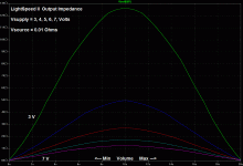
What about changing to different power supply voltages? Plots attached.
(For the LDR resistance and LED current, I only plotted the series LDR, since the shunt LDR's plots would be the same except mirrored left-to-right.)
Cheers,
Tom
(For the LDR resistance and LED current, I only plotted the series LDR, since the shunt LDR's plots would be the same except mirrored left-to-right.)
Cheers,
Tom
Attachments
Last edited:
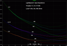
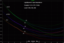
It looks like some people could consider lowering the supply voltage, slightly, if their load's input impedance is too low. See attached, which plots input impedance for loads of 20k, 33k, and 46k, with Vsupply of 4V, 4.5V, and 5V.
The peak output impedance goes higher as the supply voltage goes lower. But for 4.5 Volts the Zout peak only rises from about 2.7k (for 5.0V) to about 3.5k (for 4.5V).
EDIT: The second plot is the same thing but for 4.5V, 4.75V, and 5V. Note that the peak Output Impedances/Supply Voltages are 3.52k/4.5V, 3.06k/4.75V, and 2.72k/5V.
Attachments
Last edited:
Tom,
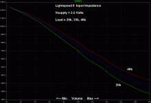
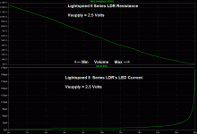
Could you repeat the test but with a voltage of 2.5volts, and also put up the resultant current/volume setting plot?
Could you repeat the test but with a voltage of 2.5volts, and also put up the resultant current/volume setting plot?
Many many thanks gootee for the wondeful plots. Now we can see much easier what exactly happens with all the lDR stuff !
BTW, I have a question:
I would like to replace the Alps pot of my headphones amplifier with the Lightspeed Attenuator. It is a G&W T2.6F hybrid headphones amp. The line input goes directly into a 100 KOhms Blue Alps pot, then goes in a SRPP 6922 tube stage (for voltage gain), then in a Classe A Mosfet output (for current).
Do you think I could just swap the Alps pot for a Lightspeed Attenuator kit without any problem with the input impedance of the SRPP tube stage ? And without having too much gain ? 😕
G&W T2.6F schematic
Last edited:
Find out what the input impedance is of the SRPP 6922 tube stage after the 100k pot you have, it should be quite high and I can see no trouble subbing the the pot for the Lightspeed Attenuator MkII circuit. Just keep it away from any heat source from tubes or transformers, and pot all 4 x NS32SR2S's together in hard wax, is will keep them thermally stable and in better calibration within a heated enviroment such as you have.
Cheers George
Cheers George
Last edited:
Thank you for the advice georgehihi ! (and for your wonderful idea !)
For the heat problem I will try to build a very small aluminium enclosure just for the 4 potted LDR's and the two cinch input connectors, and keep it outside of the amplifier with very short output signal leads going trough a hole in the amp case and directly soldered on the PCB.
And for the power supply and the control pot I will try to build them in the amp case, if I get enough place, if the heat isn't a problem for the control pot.
Cheers,
Peter
Tom,
Could you repeat the test but with a voltage of 2.5volts, and also put up the resultant current/volume setting plot?
jh,
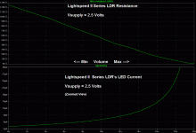
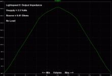
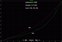
Sure. No problem. See attached plots vs volume setting for Vsupply = 2.5 Volts, showing Input Impedance for loads = 20k, 33k, 46k, the series LDR's R and Iled, the same with zoomed Iled, the Output Impedance, and the Gain for loads = 20k, 33k, and 46k.
Attachments
With the supply voltage down to 2.5 Volts, the output impedance peaks at over 27k Ohms, at the middle of the volume control range. How much of a problem would that be?
What would be the maximum acceptable output impedance, for most power amplifier inputs to work from?
What would be the maximum acceptable output impedance, for most power amplifier inputs to work from?
This is interesting, Tom
- it seems that for up to about 95% of the rotation of the volume pot, the series LEDs are using less than 30uA current - what current is the shunt led using for the same setting?
The Mark II's input impedance ranges from 125kR down to about 30kR and extrapolating from the plots, it would seem that a 100kR load would nearly be linear and range from the same 125kR down to about 60kR - and, from the gain plot (last photo), a 100kR load would also be more linear - a wonder if we could use this somehow?
Could you extend your model to add another series LDR with the same properties as the first series one to give the classic T-pad and do the same measurement, particulkarly with attention to see if the humped o/p impedance also becomes more linear? Not sure if this is possible with your model as most T-pads have different series/shunt coefficients/ratios but ....
Didn't you develop a simple low current control mechanism for the L/Speed somer years ago? Did it function okay?
Thanks for going to so much trouble, and it is quite interesting indeed.
I've evaluated various iterations of teh lightspeed over the last few years including:
1. Standard with 5V
2. ALWSR for 5V
3. CCS supplied
To my ears the constant current source driven lightspeed sounded the best, with a level of detail and "transparency" that was unrivalled.
Any idea if there are CCS driven lightspeed kits out there?
Is anyone selleing balanced pre-amp kits?
1. Standard with 5V
2. ALWSR for 5V
3. CCS supplied
To my ears the constant current source driven lightspeed sounded the best, with a level of detail and "transparency" that was unrivalled.
Any idea if there are CCS driven lightspeed kits out there?
Is anyone selleing balanced pre-amp kits?
Any idea if there are CCS driven lightspeed kits out there?
See: Lighter Note Kit - ALL YOU NEED
and Google "The Lighter Note + LDR" for info/reviews.
- Home
- Source & Line
- Analog Line Level
- Lightspeed Attenuator a new passive preamp
