The views are very opposing, perhaps it has been done. I know the quotes sure are contradictory and I see this kind of attack happening when someone has a product that competes with George's and they want to devalue Lightspeed, then famously come out with their brand new superSpeed (TM) or LightWonder (TM) lol that claims to solve the worlds problems while they stomp on George's thread. It happens a lot recently and I think anyone who wants to bandy their own product ought to do it in their own thread. I realize I post here a lot and I have my own product but I dont shout about it on this thread, or any other for that matter, and I am only here to encourage people to use LDRs and to appreciate what George has given us. Maybe thats whats going on with our most recent man with only test equipment for ears, maybe not, but the guy posted a few times about trying to design what I felt was a new LDR product so I get immediately suspicious when someone shows they intend to build a product after finding out how wonderful LDRs are, then they have negative stuff to say. Maybe I am completely wrong and this guy just has other issues, I dunno.
By the way if anyone has doubts about LDRs you really should, obviously listen, but secondarily you should view the thread George linked a few posts back in which Jackinnj tested various LDRs and posted their noise level. Its ridiculously low and shows this product is wonderful for audio.
Uriah
By the way if anyone has doubts about LDRs you really should, obviously listen, but secondarily you should view the thread George linked a few posts back in which Jackinnj tested various LDRs and posted their noise level. Its ridiculously low and shows this product is wonderful for audio.
Uriah
Well, he's online right now and on this thread so probably there will be a good explanation.
Another thing to add is that if people are having noise problems with their LDRs they need to make sure they are not overdriving them first of all. Next you need to make sure you are not using a pot that cant handle the CURRENT, not just the V*A and if the wiper makes poor contact that can screw it up audibly as well. Finally, your power supply is probably the culprit. Best sound is from a linear supply with a very good noise killing circuit. If you use wallwarts (most), SMPS, transformers near the LDRs you are going to have noise. It doesnt make sense when we think that we are just lighting an LED but the noise from the supply gets in there. A LDR customer sent me a cell phone photo of his scope which clearly showed noise with a noisey supply. Clean your supply and every improvement is audible. Another thing to do is turn off those light dimmers in the house. When I have bzzz on my system I turn the lights off downstairs (nearly all have dimmers) and instantly the bzzz is gone. Someone please explain to me how a resistor, just one in the signal and one to ground, is going to cause inexcusable noise.. Its not. But if you put noisey stuff right next to it then, yeah, you might suspect the resistor.
Uriah
Well, you forget to mention two important things... First the dates of these posts and secondly several other posts not originating from me. I personally think that you aways must go further and not stop on the way. I first listen to the LDRs and then I tried to improve the schematics with another guy. After this second step, we did measurements...
Then again, but I think I'm waisting my time to try to explain one more time this point, the sound of the LDR isn't "bad" definitely, please check my lasts posts. But, for scientific reasons as explained, I think the distortion results obtained by this preamp and the lack of a good buffer are, again in my opinion, not at acceptable levels to derive a high quality device...
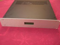
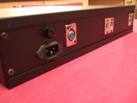
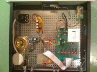
Here some picts of my own design !...
Then again, but I think I'm waisting my time to try to explain one more time this point, the sound of the LDR isn't "bad" definitely, please check my lasts posts. But, for scientific reasons as explained, I think the distortion results obtained by this preamp and the lack of a good buffer are, again in my opinion, not at acceptable levels to derive a high quality device...
Here some picts of my own design !...
Attachments

I was sure there was a product involved and there was no doubt in my mind it had the word "speed" in it.
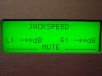
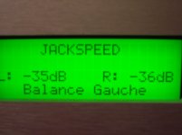
This balanced preamp is of course totally remote controlled with all the functions of such a device (volume, balance, mute, etc.). The control window was opened by a "very high precision water jet cutting system"...
The calibration in this model is totally hand made. In another single-ended version we developed an automatic calibration of the ADCs with different timing selection for the procedure for an hour to... a day !...
As you can see for a 25 dB attenuation, the values of distortion are definitely too high... But it seems others found the same results (M. Pass for example).
I hope I have given enough evidences of our personal work on this project...
Last edited:
is this the first of the many pages of evidence to support your earlier assertions that you are going to insert into your own JACKSPEED Thread?Finally, here are some distortion values obtained on an Audio Precision device :
...and there was no doubt in my mind it had the word "speed" in it.
I'm guilty as well!

I was sure there was a product involved and there was no doubt in my mind it had the word "speed" in it.
Finally you know all things and have a business to fight for...
I have nothing to sold. I did it for the fun and I report here for free and to inform of our personal results after a couple of years playing with these components.
No more, no less...
I'll be happy to give you more info if requested.
Oh and please look forward : you'll never see any thread on a "X-speed" originating from me in the future. Never...
Last edited:
Trying to attack a balanced Lightspeed, will have a concussive affect on ones mind.
Cheers George
Cheers George
I don't understand "ondesx" you asked me many questions on how to match, calibrate etc on your diy Lightspeed like a virgin on her first night.
Yet you know how to drive an "Audio Precision" analyser and measure your results, something does not gel here.
Cheers George
Yet you know how to drive an "Audio Precision" analyser and measure your results, something does not gel here.
Cheers George
Is the word "hustling" a good expression for that?I don't understand "ondesx" you asked me many questions on how to match, calibrate etc on your diy Lightspeed like a virgin on her first night.
Yet you know how to drive an "Audio Precision" analyser and measure your results, something does not gel here.
Cheers George
I don't believe "ondesx" has any "Audio Precision" measured data stored for retrieval in any form. It think if he has, some curves tell more than such simplistic hand-jotted numbers.
Additionally, there are many things involved in determining what effects the listening experience, at least this is what I discover when working with cables. Unless one has found the dominating issues and sort them out, the distortion numbers mean almost nothing.
I don't believe "ondesx" has any "Audio Precision" measured data stored for retrieval in any form. It think if he has, some curves tell more than such simplistic hand-jotted numbers.
Here are some additional AP curves... The other are too big to be posted. You "don't believe" I have AP measurements... You "Believe" in what your ears tell to you... Believe, don't believe... Where is science here ?...
What do you want now : the serial number of the device ? Some blood sample of the guy who build it ?
Attachments
I don't understand "ondesx" you asked me many questions on how to match, calibrate etc on your diy Lightspeed like a virgin on her first night.
Yet you know how to drive an "Audio Precision" analyser and measure your results, something does not gel here.
Cheers George
Dear Georges,
I think there are several things you don't understand. But it's the same for me. And it doesn't matter at least. Everybody can learn. And I learn a lot from the time of the first questions. Do you improve your own knowledge on the behavior of these components from the beginning ? Do you made measurements to try to understand what is going on ? I and several other did it. We report here our results. There is no personal attack in these posts. If you just open a thread to hear people saying good things about the project, please write somewhere that on this forum it is not allowed to criticize or report divergent results...
Hope you are smart enough to understand that these are just scientific results. Forget any personal intention. I'm sure this will profit to everyone... I mean even to you !
My Best.
Lot's of people in this forum know that I provide more data in combination with listening impressions than most care to do. To only look at distortion data is misleading, as I have discovered during cable testing. Additionally, setup configuration effects the results as well. We have no knowlege what are the exact circuits of comparison, circuit configuration and exact values also effect results.Here are some additional AP curves... The other are too big to be posted. You "don't believe" I have AP measurements... You "Believe" in what your ears tell to you... Believe, don't believe... Where is science here ?...
What do you want now : the serial number of the device ? Some blood sample of the guy who build it ?
I will study your plots a bit more, but it seems like scanned paper rather than direct pdf printout from AP data. So it seems the work was done not by yourself?
I will study your plots a bit more, but it seems like scanned paper rather than direct pdf printout from AP data. So it seems the work was done not by yourself?
The printer was a bit out of ink. The outputs of the printer were scanned to be converted in pdf... These measurements were made in my presence by a professional audio engineer working in the audio lab owning the AP... The results obtained can't be discussed and the "circuit" was of course the "standard" series-shunt model.
Don't try to look behind the facts. Instead, try to understand what is going on... I think we'll go ahead all together if we forget to fight one against the others and help each other!
First of all, for the "standard series-shunt model", were all test items using the same resistance value? Do you have impedance-frequency curve data? For "standard series-shunt model", the input impedance varies with position. Were the test leads standard 50 Ohm impedance cables? What was the output impedance of the signal source? What was the load impedance on the output of this "standard series-shunt model"?
I am only curious because from my listening experience coupled with measurements, the way LDRs sounded should be such that measureable improvements can be seen.
I am only curious because from my listening experience coupled with measurements, the way LDRs sounded should be such that measureable improvements can be seen.
Last edited:
Real Audio Precision measurements you can trust;
Here are proper Audio Precision measurements done by Nelson Pass, which are at worst .1% at full cd output of 2v rms.
Typicaly from a cd source you will get 500mV to 1volt playing cd's and at that level it's down to only .01 to .05% and these are 2nd harmonic which are pleasing to the ear like so many tube pre and power amps, which can give over 1%. And then there's the speakers which are even worse.
Then there's Jackinni's real AP measurments http://www.diyaudio.com/forums/analog-line-level/177332-comparison-light-dependent-resistors.html
`
Attachments

Last edited:
Pass LDR distortion results
Does the -0dB plot show that at high signal levels that the added distortion from the LDR is essentially zero%?
Looking at the top -10dB plot. Where it passes 2V, it shows 0.1% distortion. Is this input voltage or output voltage?
Does the -0dB plot show that at high signal levels that the added distortion from the LDR is essentially zero%?
Looking at the top -10dB plot. Where it passes 2V, it shows 0.1% distortion. Is this input voltage or output voltage?
- Home
- Source & Line
- Analog Line Level
- Lightspeed Attenuator a new passive preamp