Hello again
I have spent some time going over the strip board this evening, I've checked for shorts and everything seems to be wired correctly. What is the best way to check the LDRs are working whilst in the circuit?
Thanks
I have spent some time going over the strip board this evening, I've checked for shorts and everything seems to be wired correctly. What is the best way to check the LDRs are working whilst in the circuit?
Thanks
put 5V through a large resistor, maybe 50k for example, to the positive lead of one LDR then GND to the other. Measure the resistance of that LDR. Lets see what you get. Should be some decent resistance. If you are in the 100ohm range something is wrong..... OOOOhh. You are using the SR3. Most of us have no experience with these and I dont know what is the proper resistance. Maybe 100k pot works fine, I dont know but they have a huge range compared to SR2 so maybe this has something to do. Not sure.
But try that test. Also make sure GND is actually GND and goes only to the dots like George said. Then check that your signal wiring is correct. I wonder if for some reason your Shunt LDRs are dark and your Series are bright.
Uriah
But try that test. Also make sure GND is actually GND and goes only to the dots like George said. Then check that your signal wiring is correct. I wonder if for some reason your Shunt LDRs are dark and your Series are bright.
Uriah
100R you need one in front of each LDR positive leg. Just as always. The series one should be between 10 and 30 and you could even go lower. It only adjusts overall impedance of the circuit. There is no protection in the series resistor. You can leave it out. If you will try it then use a trimmer and then replace with the value you settle on. I suggest build it the way George has shown us on page 4 and then tweak with a small value series resistor if you find that to your liking. If its perfect for your system without the series resistor then leave it out.
Uriah
Uriah
OK will give it a go. I like the sound as it is, but I don't have a lot of travel on the pot.
That is where a small value resistor might be helpful. If you go to high with that series resistor you get super high resistance at either extreme of pot rotation. Try a 100R trimmer as the series resistor to find what is best for you. Then replace with a regular resistor for longer life.
Uriah
Uriah
put 5V through a large resistor, maybe 50k for example, to the positive lead of one LDR then GND to the other. Measure the resistance of that LDR. Lets see what you get. Should be some decent resistance. If you are in the 100ohm range something is wrong..... OOOOhh. You are using the SR3. Most of us have no experience with these and I dont know what is the proper resistance. Maybe 100k pot works fine, I dont know but they have a huge range compared to SR2 so maybe this has something to do. Not sure.
But try that test. Also make sure GND is actually GND and goes only to the dots like George said. Then check that your signal wiring is correct. I wonder if for some reason your Shunt LDRs are dark and your Series are bright.
Uriah
OK, I soldered a spare LDR to a 47k resistor wired in series with the 5v supply and I am getting a reading of 1K5

The test needs to be on the ones in your circuit. One of the 4 looks backward by the way.
Did you test to match these guys before putting them in the circuit so you could know what pot to use? You might possibly have a 4k pot here which might not be best for your system.
Uriah
Did you test to match these guys before putting them in the circuit so you could know what pot to use? You might possibly have a 4k pot here which might not be best for your system.
Uriah
The test needs to be on the ones in your circuit. One of the 4 looks backward by the way.
Did you test to match these guys before putting them in the circuit so you could know what pot to use? You might possibly have a 4k pot here which might not be best for your system.
Uriah
I bet you chuckled at that! 🙂
I wanted to check a random LDR out of the circuit to see what value it was.
The LDR isn't backward, this one has SR3 printed on both sides where as the others have SR3 on one side and 309 on the other. The dot is on the right side.
I have just checked the first LDR and its 1.567K, i'll now check the other three
When you are done with that then turn your Lightspeed off. DMM goes to first gang or second gang of your pot. Turn it to 47k. Now turn on LSA and measure associated LDRs. You wont probably get anywhere near the same reading because when you turn on the LSA the voltage drop across the LDRs will send their resistance higher, but anyway at least make sure their resistance is higher than what you measured them at.
Uriah
Uriah
when you are done with that then turn your lightspeed off. Dmm goes to first gang or second gang of your pot. Turn it to 47k. Now turn on lsa and measure associated ldrs. You wont probably get anywhere near the same reading because when you turn on the lsa the voltage drop across the ldrs will send their resistance higher, but anyway at least make sure their resistance is higher than what you measured them at.
Uriah
First Test
1=1.567K
2=0
3=1.390K
4=0
Second Test (Pot set to 47K)
1=3.69K
2=0
3=3.5K
4=0
I am going to assume that 2 and 4 are your shunt resistors and that 0 means no reading. See the shunt go to ground and when full signal passes ground some of the signal is tempted to go to ground rather than to your amp. If the resistor is off then there is nothing enticing about going to ground so full signal continues on to your amp.
When series is high and shunt is low then volume is low and the reverse is true.
I dont know why your shunt are either dead or not lighting up.
Uriah
When series is high and shunt is low then volume is low and the reverse is true.
I dont know why your shunt are either dead or not lighting up.
Uriah
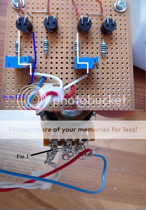
Maybe you could tell us about the wires under the board. Where they go, where they come from. We can assume this but assuming is what leaves the questions unanswered so far 🙂
Uriah
Uriah
I am going to assume that 2 and 4 are your shunt resistors and that 0 means no reading.
You assume correctly!
I am going to retire for the evening as its quite late here. I will have another look when my eyes are not so bleary.
Thanks for your help today 🙂
Richard

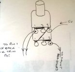
I can see you have wired pot as pr original schematic
Do you rely on the numbering being right, or have you measured your pot
I would disconnect the pot, and measure it
Hi Tinitus
I think the pot is correct because I am using the same as Puffin, but that's no guarantee 😉
Tyco Pot
http://uk.farnell.com/jsp/search/productdetail.jsp?SKU=1173987
Richard
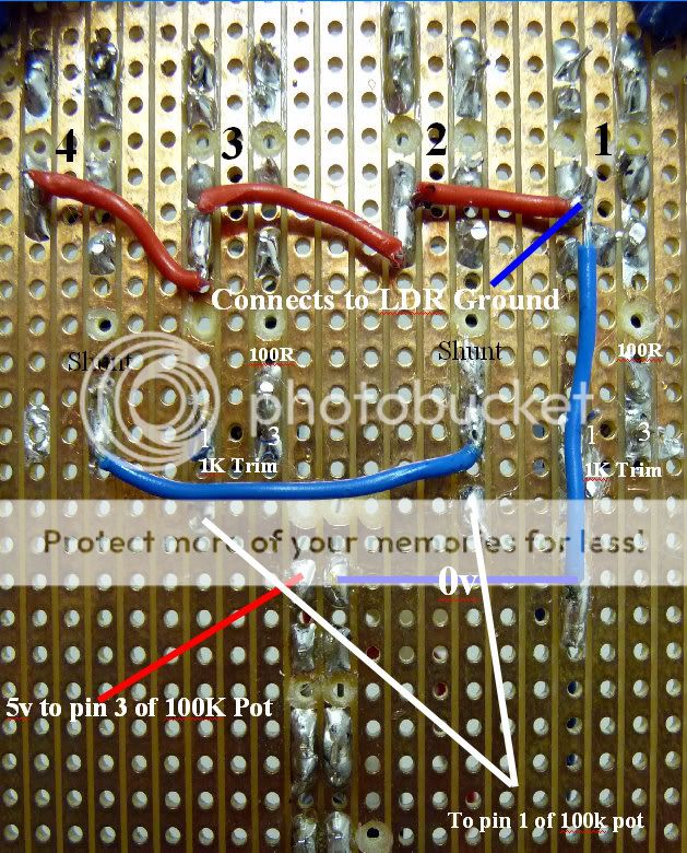
I dont see any power going to positive pins of LDR 1 and 3.
Uriah
I have soldered pin 2 to 3 on the 1K trim pot
I hopes this helps
Thanks
Richard
edit: I have just noticed the white lines to the 1k pot has moved slightly to the left and right. The white wire from pin 1 of the 100k pot connects to pin 1 of the 1k trim
Last edited:
- Home
- Source & Line
- Analog Line Level
- Lightspeed Attenuator a new passive preamp