Tripmaster,
In your measurement diagram earlier, you had 0 voltage at the shunt's.
If it is indeed 0 voltage, it is wrong because none of the voltage can reach zero.
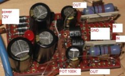
If I read it right, the #2 and #4 shunt's are fed from the blue line. Can you measure
directly at the pot for the voltage of this pin? This voltage should read non zero and varies as the pot is turned.
In your measurement diagram earlier, you had 0 voltage at the shunt's.
If it is indeed 0 voltage, it is wrong because none of the voltage can reach zero.
If I read it right, the #2 and #4 shunt's are fed from the blue line. Can you measure
directly at the pot for the voltage of this pin? This voltage should read non zero and varies as the pot is turned.
Tripmaster,
In your measurement diagram earlier, you had 0 voltage at the shunt's.
If it is indeed 0 voltage, it is wrong because none of the voltage can reach zero.
If I read it right, the #2 and #4 shunt's are fed from the blue line. Can you measure
directly at the pot for the voltage of this pin? This voltage should read non zero and varies as the pot is turned.
Hi Fred
Thanks for taking the time to look at this. I'm in the process of tidying the study, as soon as this is done I'll check and let you know.
Regards
Richard
Do you mean the voltage from the anode pin of the shunt LDR to ground?Hello again
The voltage changes from 5v to 4.96v on a complete turn of the 100k pot
Richard
Richard,
hopefully Fred or another can take you all the rest of the way through this. I have company til midweek.
Good luck and I will help if I think of anything
Uriah
hopefully Fred or another can take you all the rest of the way through this. I have company til midweek.
Good luck and I will help if I think of anything
Uriah
HI Richard,
Try the following to see you can get a little closer to the source of the problem:
1. Attach the probe at the LED legs of the shunt LDR's. I believe you got 0
earlier. Just to be sure this is the case as I could misread from previous posts.
If you get reading of meaning voltage, then watch the voltage while turning
pot, you should see the voltage going down. If you do see 0V regarding to the
pot position, try #2 and #3.
If it is the case that you got 5V -> 4.96V, then do #3 and measure the 100R.
You should not see almost full 5VDC at any LDR.
2. Attach one probe to the in where the blue wire is solder to the pot and
one probe to the anode pin of the shunt LDR. I think the blue wire is
the PS to the shunt's. This is just to check the connectivity from the
pot to the LDR.
3. Let say there is continuity measured from #2 (should be resistance).
Then power off the unit and put one probe at the blue wire pin and
the other at where the 5V input pin. Turn the pot, check to see the
resistance vary. If this also varies the resistance, then I suspect
Give the above a try and see there is any hint found.
Do you mean the voltage from the anode pin of the shunt LDR to ground?
I connected my meter between the power supply ground and the blue wire terminal on the pot. I have have also connected the meter to the anode pin of the shunt ldr. Both result in same reading
Hmm, you should not get almost 5V at the anode when the 100R is present, also the pot should provide a much wider range of the voltage.I connected my meter between the power supply ground and the blue wire terminal on the pot.
I have have also connected the meter to the anode pin of the shunt ldr. Both result in same reading
My wild guess is,
- it is not a 100K pot, or it is defect
- the 100R resistor is not 100R, way lower.
- The LDR's are dead and draws very very small current that make
no dent in the voltage dropped. I hope I am completely wrong, but
there is a good chance unfortunately because at this voltage, there
should be close to no resistance. When the shunt has no resistance,
you get silent instead of full volume .....
Try step #3 from my last post to measure the pot, and measure the resistor.
PS: If the LDR's get 5V at the anode, it won't survive. Don't power it up again
until the measurement of the rest of the components are good.
HI Richard,
Try the following to see you can get a little closer to the source of the problem:
1. Attach the probe at the LED legs of the shunt LDR's. I believe you got 0
earlier. Just to be sure this is the case as I could misread from previous posts.
If you get reading of meaning voltage, then watch the voltage while turning
pot, you should see the voltage going down. If you do see 0V regarding to the
pot position, try #2 and #3.
If it is the case that you got 5V -> 4.96V, then do #3 and measure the 100R.
You should not see almost full 5VDC at any LDR.
1=1.49-1.74v
2=4.96-5.00v
3=1.49-1.74v
4=4.96-5.00v
Hmm, you should not get almost 5V at the anode when the 100R is present, also the pot should provide a much wider range of the voltage.
My wild guess is,
- it is not a 100K pot, or it is defect
- the 100R resistor is not 100R, way lower.
- The LDR's are dead and draws very very small current that make
no dent in the voltage dropped. I hope I am completely wrong, but
there is a good chance unfortunately because at this voltage, there
should be close to no resistance. When the shunt has no resistance,
you get silent instead of full volume .....
Try step #3 from my last post to measure the pot, and measure the resistor.
PS: If the LDR's get 5V at the anode, it won't survive. Don't power it up again
until the measurement of the rest of the components are good.
It is a 100k pot but I have another
All four 100R resistors spot on
Last edited:
HI Richard,
3. Let say there is continuity measured from #2 (should be resistance).
Then power off the unit and put one probe at the blue wire pin and
the other at where the 5V input pin. Turn the pot, check to see the
resistance vary. If this also varies the resistance, then I suspect
0-94.8K with a full sweep of the pot
1 and 3 look normal, 2 and 4 are not. 2 and 4 should measure like 1.74V - 1.49V.1=1.49-1.74v
2=4.96-5.00v
3=1.49-1.74v
4=4.96-5.00v
Try this to confirm the health of #2 and #4:
1. Disconnect the power supply into #1 and #3.
2. Add a 500K resistor in series to the 100R, and connect the 5V to the 500K
something like
LDR anode <---> 100R <---> 500K <---> 5VDC.
Measure the anode voltage and voltage across 500K.
If you don't have 500K, use some high value resistors.
The idea is to see how much current the LDR's draw.
1 and 3 look normal, 2 and 4 are not. 2 and 4 should measure like 1.74V - 1.49V.
Try this to confirm the health of #2 and #4:
1. Disconnect the power supply into #1 and #3.
2. Add a 500K resistor in series to the 100R, and connect the 5V to the 500K
something like
LDR anode <---> 100R <---> 500K <---> 5VDC.
Measure the anode voltage and voltage across 500K.
If you don't have 500K, use some high value resistors.
The idea is to see how much current the LDR's draw.
BTW, do one LDR at a time.
I have used a 469K resistor
Attached DMM to Cathode and Anode of LDR
2=4.61-4.78v
Attached DMM between 460K and Anode of LDR
2=4.79-5.00v
Attached DMM to Cathode and Anode of LDR
2=4.61-4.78v
Attached DMM between 460K and Anode of LDR
2=4.79-5.00v
Hi Richard,I have used a 469K resistor
Attached DMM to Cathode and Anode of LDR
2=4.61-4.78v
Attached DMM between 460K and Anode of LDR
2=4.79-5.00v
It doesn't look good. The test circuit that I asked you to try is the simpliest way to test a LDR. With almost 500K between the LDR and the PS, it only dropped 0.2V. You will have to drop at least another 2.3V to keep them in the safe zone. Even they are not defected, you are likely need a high impedance pot, say 10M, to operate, but definitely not a match to the other pair of LDR's.
If you have another pair of LDR's other than the series pair. You can test them out using the simple test circuit. You will get different reading.
Hi Richard,
It doesn't look good. The test circuit that I asked you to try is the simpliest way to test a LDR. With almost 500K between the LDR and the PS, it only dropped 0.2V. You will have to drop at least another 2.3V to keep them in the safe zone. Even they are not defected, you are likely need a high impedance pot, say 10M, to operate, but definitely not a match to the other pair of LDR's.
If you have another pair of LDR's other than the series pair. You can test them out using the simple test circuit. You will get different reading.
Hi Fred
Thanks for checking. I have 6 more LDRs and will test and replace as suggested

Richard
the LDR part is in the AUDIO circuit.
It should ONLY have audio signal (AC music) on it.
It should NEVER have DC on it.
The LED half sees a DC current/voltage.
Because it is a LED it has near constant voltage drop across it.
~2V but I have not measured it yet.
That voltage will vary as the current passing varies.
Low currents pA will give low voltage, maybe 200mV less than rated LED voltage.
high currents mA will give high voltage ~rated LED voltage.
The voltage across the LED should be ~ 2V+0-200mVdc
The voltage across the LDR should be audio only ~100uVac to 2000mVac.
- Home
- Source & Line
- Analog Line Level
- Lightspeed Attenuator a new passive preamp