Lightspeed remote control
Hi folks,
The CAD files for the voltage controlled current source (VCCS), IR transmitter (IRT1A) and IR receiver (IRR1A) are all in the hands of the printed circuit board manufacturer. Not long to go now!
I have a price for the two IR boards now and these will cost £13.77 for the pair including the application note. I have not had time to check the material costs of the built and tested IR modules yet. I will try to get this done this weekend and will post the information as soon as it is ready.
The prices quoted for insured shipping and packing in post 1706 will cover a full set of boards as the total weight is still under the next price threshold.
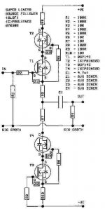
For those who want a high performance buffer for their Lightspeed volume control but would prefer not to work with the dangerous high voltages used in the Super Linear Cathode Follower (SLCF) I have a depletion mosfet circuit version for you based on the SLCF topology.
I have been using this circuit in various designs since IXYS launched their depletion mosfets and can vouch for it’s excellent audio performance. Sorry the BSP149 is surface mount but Infineon seem to think that the world no longer needs the leaded version. It is possible to hard wire the BSP149 into the circuit without too much hassle. Just make each supply rail about 10 volts higher than the maximum peak voltage swing you require to allow some headroom for the cascode. Quiescent current is around 50ma and this can be increased if desired by reducing the value of R3 and R10 (keep them the same value). The IXYS mosfets may need a heatsink depending on the voltage rails and quiescent current settings.
Regards
Paul
Hi folks,
The CAD files for the voltage controlled current source (VCCS), IR transmitter (IRT1A) and IR receiver (IRR1A) are all in the hands of the printed circuit board manufacturer. Not long to go now!
I have a price for the two IR boards now and these will cost £13.77 for the pair including the application note. I have not had time to check the material costs of the built and tested IR modules yet. I will try to get this done this weekend and will post the information as soon as it is ready.
The prices quoted for insured shipping and packing in post 1706 will cover a full set of boards as the total weight is still under the next price threshold.
For those who want a high performance buffer for their Lightspeed volume control but would prefer not to work with the dangerous high voltages used in the Super Linear Cathode Follower (SLCF) I have a depletion mosfet circuit version for you based on the SLCF topology.
I have been using this circuit in various designs since IXYS launched their depletion mosfets and can vouch for it’s excellent audio performance. Sorry the BSP149 is surface mount but Infineon seem to think that the world no longer needs the leaded version. It is possible to hard wire the BSP149 into the circuit without too much hassle. Just make each supply rail about 10 volts higher than the maximum peak voltage swing you require to allow some headroom for the cascode. Quiescent current is around 50ma and this can be increased if desired by reducing the value of R3 and R10 (keep them the same value). The IXYS mosfets may need a heatsink depending on the voltage rails and quiescent current settings.
Regards
Paul
Attachments
Paul,
I'm ordering parts to build my B1 and was wondering what the voltage requirements are for the VCCS so I can design my voltage regulator.
I'm ordering parts to build my B1 and was wondering what the voltage requirements are for the VCCS so I can design my voltage regulator.
I just sent you 28 GBP for a pair(2 tx, 2 rx). If I read your post correctly you said they would be included in the shipping of the original PCB?
Troy if I read it correctly there is a shipping fee. Post 1707.
Uriah
edit:
I think the VCCS takes 12V/0V
Then your B1 can run just about anything. I have read that it sounds best at 10V. Recommended is 18V but I think I remember seeing it could handle even 40V. So maybe throw a LM317 at that with a variable resistor and just see what sounds best but dont go past 75% of what your caps can handle.
"The prices quoted for insured shipping and packing in post 1706 will cover a full set of boards as the total weight is still under the next price threshold."
This is why I asked..
"packing in post 1706 will cover a full set of boards as the total weight is still under the next price threshold."
But I can send more if required.
This is why I asked..
"packing in post 1706 will cover a full set of boards as the total weight is still under the next price threshold."
But I can send more if required.
udailey said:
edit:
I think the VCCS takes 12V/0V
Then your B1 can run just about anything. I have read that it sounds best at 10V. Recommended is 18V but I think I remember seeing it could handle even 40V. So maybe throw a LM317 at that with a variable resistor and just see what sounds best but dont go past 75% of what your caps can handle.
Uriah, the transformer you sent me puts out 1A @ 12V. That should be enough to power the B1 and the VCCS.
Also, if I'm integrating the Lightspeed into my B1, do I need the VCCS and IR boards or just the IR boards? I'm a little confused.
😕
You need the VCCS boards as well. You could use or not use the IR boards. They are only for remote control of the volume. Instead you could use two momentary switches to control the DS1802 on the VCCS boards or you could just make the LSA the way George has it in his schematic on, I think, page 4 but maybe a page or so earlier. All you absolutely need is some 5V/0V DC source, a 100k dual log pot, 4 100ohm resistors, a 1k trimpot, and the LDRS. But you would need all this with or without the B1.
The transformer should be giving you 24V. Did you check the web for its schematic?
Uriah
The transformer should be giving you 24V. Did you check the web for its schematic?
Uriah
Lightspeed remote control
Hi folks,
There seems to be some confusion regarding the VCCS remote control project.
I decided originally that, as there were several low cost, 4 channel IR kits available on the internet, it would not be financially viable for me to do IR boards and modules. I just don't have the buying power to get a competitive price. This was all discussed earlier in the Lightspeed thread. I was only going to offer the unique part of the project (the VCCS board or module). This has been cost assessed to cover materials (and assembly labour in the case of the module) but I have not included development costs or business profits in the pricing equation. Essentially this project is a non-commercial group buy offered as a diy project in the same spirit as George divulging details of his Lightspeed design.
However, since the project began, I have had a number of enquiries about providing a complete IR solution, and, as I wanted a tidy IR unit myself, I decided to offer boards and modules for this as well, to those who wished to have a project with all the hassles of mix and match already ironed out. The transmitter board has been designed to fit in a presentable “off the shelf” extruded aluminium case and I have chosen a really solid 4 way keypad by Storm that has etched cursors that should last a lifetime (I’m fed up of inadequately constructed remote controls that fall apart at the slightest provocation). You do not have to use the Storm keypad, just 4 push button momentary switches, of whatever design you fancy and you can also use a different case if you wish. I will be using 4 nickel metal hydride rechargeable batteries in my remote control and a DC connector can be fitted to the case to allow an “off the shelf” battery charger to be used. This is more cost effective in the long term than buying standard batteries.
The VCCS board provides stereo control with volume up, volume down, balance left and balance right, just as the DS1802 would be used, if configured as a standard volume control with balance function. You can also interface the DS1802 to a computer for control as described in the Dallas application note. The VCCS board has two sets of control connectors wired in parallel so you can connect the IR receiver and you can also connect a keypad mounted on your chosen preamp case (or individual push button switches) at the same time. This means that the volume can be controlled from the remote or the preamp. It also means that you do not have to have a remote if you do not want to. Just fit push button switches on the preamp.
The VCCS board has a three terminal 12 volt regulator on board and you will need to feed the board with a DC voltage of around 17 volts allowing for mains voltage variation. A transformer with a 12 volt ac secondary, when rectified and smoothed will provide a voltage of approximately 17 VDC.
Regards
Paul
Hope Paul doesnt mind.
Thought I would recap his pricing in case the last post peaked anyones interest again.
" Lightspeed remote control Post #1706
Here is information about carriage and packaging charges for the VCCS board/module shipping. I will use the first class signed for service in the uk and international signed for airmail for europe and the rest of the world.
UK VCCS board �2.24
UK VCCS module �3.00
Europe VCCS board �5.74
Europe VCCS module �6.63
Rest of world VCCS board �6.14
Rest of world VCCS module �7.33
These carriage charges will have to be added to the board/module cost.
Also please remember to send funds in GBP (pounds sterling) as Paypal will charge me for conversion if you do not do this. "
The VCCS boards are GBP 12 and the IR boards are GBP 13.77 for the pair.
So if you wanted to do the LSA with VCCS and remote control boards it would cost you GBP 25.77 plus shipping. Then you would have to buy LDRs and a remote control case, a preamp case, and some momentary switches.
You can get the Silonex LDRs from Allied for about $3.75 each for the sorted ones and I think $2.29 for the unsorted. You will need 4 of them. 2 for each channel and the series must be matched and the shunt must be matched. I would order a minimum of 25 of them to get 2 well matched pairs. Remember while its great to have the series also match the shunt it really doesnt matter. Consider how an attenuator works and you will see why this really is not an issue. The two sides of an regular log pot only match at one point on an endless number of possibilities but the total of their two sides always end up equaling the total resistance of the pot. With the LDRs we do essentially the same thing. The series increases in resistance at the same rate as the shunt decreases so for the most part the total resistance of the two LDRs is the same at all volumes if you were to add the resistance of the shunt and the series together.
Well, I want everyone to know that I have recieved 100 of my 300 LDRs and have been home a few days. I have 200 ordered and they shipped yesterday. I have changed my testing method. Previously I had been testing the LDRs in parallel with one resistor in series with the + bus. Worked quite well but I have been reading about LEDs in parallel and it seems that if you continue testing in that way then the resistance of each LED will allow one LED to take more power than another so its possible for a single test on several LDRs to allow one LED to emit more light than another. This shouldnt worry anyone who already recieved LDRs since I did actual listening tests on each set I sent out.
I want this test to more closely resemble the actual environment the LDRs will operate in when you use them in a LSA. So, I ordered a few hundred trim pots in values from 1k to 50k and will test in 5 different steps, setting each trimpot to a resistance perfectly equal to each other trimpot and then putting the trimpots all on the + bus and putting each LDR in series with one single trimpot then put all LDRS on the - bus. This way they each have no opportunity to see a different resistance inbetween the LDR and the power supply. It will make for the most accurate testing that I can do.
I had intended to start testing on the 5th but after thinking about my test setup I decided to wait til I get all these trimpots and then to work on setting up a new test rig on this Monday and start testing on Tuesday or Wednesday. I think it will go faster as well so I dont think there will be any delay in getting your LDRs.
Cheers Guys and Gals
Uriah
Has anybody created a microprocessor based system yet whereby any two unmatched LDRs can be used and the system firstly calibrates them & stores the profile for each, thereby allowing any volume setting to have accurate tracking between the two? Calibration could be done any time thereby dealing with possible ageing of the components. I know it makes a beautifully simple concept into a much more complex offering but think of all the wasted unmatched ldrs there must be sitting in people's junk boxes!
If you buy enough they dont get wasted 🙂 Eventually they will all have a match. Well, almost all I think.
I asked Maximus indirectly about that a few pages back. I am not capable and he did not seem to think it was worth the extra work/components and frankly unless it is a commercial venture I dont see where it would be an advantage work and costwise. We have the trimpot to make up for small discrepancies.
But if you have the skills it still might be fun!
Uriah
Hi John
I've only done half the job you propose. (see post #1660) I just bought the needed LDRs, no more. Each step is hand matched in circuit with a specific dac word per channel.
Being over fifty years old, i've engineered my preamp to match my own ageing. In my R-LDR release, less LEDs efficiency will lead to a higher audio level that should compensate for my own ears losses. And the relative false readings on my LCD display should give me the impression of a still good hearing... 😉
Cheers
Francis
But Uriah, it would avoid having to buy a batch to get a match - if you need 2 why buy 25?
Secondly, I don't know if the LDRs age & slip out of spec with each other - this would again be prevented by running a calibration whenever liked.
Thirdly, it's probably the only practical way to get a multi-channel vol control.
Francis, I'll have a look at post #1660
Secondly, I don't know if the LDRs age & slip out of spec with each other - this would again be prevented by running a calibration whenever liked.
Thirdly, it's probably the only practical way to get a multi-channel vol control.
Francis, I'll have a look at post #1660
No, I definitely agree with you about 2 vs 25!! I think its a great idea if you have the skills. If you can do it I am psyched and would love to have one.
Uriah
Uriah
Postage for both VCCS & IR
Paul,
I was wanting to order two complete set of boards i.e. 2 x VCCS board and 2 x set of IR boards, could you please let me know the Postage details for this (I am in the UK) - if other people are doing this (i.e. VCCS & IR) then could you publish a new set of figures?
Regards
Alan
Paul,
I was wanting to order two complete set of boards i.e. 2 x VCCS board and 2 x set of IR boards, could you please let me know the Postage details for this (I am in the UK) - if other people are doing this (i.e. VCCS & IR) then could you publish a new set of figures?
Regards
Alan
jkeny said:But Uriah, it would avoid having to buy a batch to get a match - if you need 2 why buy 25?
I ordered 10 matched and found 4 matched pairs. No problem.
wlowes,
were you lucky? What's the average hit rate? You can't get suppliers to agree to pick parts from the same batch, they will all refuse to do this.
Even when you have a matched pair there is a certain divergence between them at various points in the curve! This may be no worse than a normal dual pot but wouldn't it be nice to have both channels match exactly all through the vol range?
- Home
- Source & Line
- Analog Line Level
- Lightspeed Attenuator a new passive preamp