Mike, did you solve the DC noise with the current source setup? Is the higher 12 volt supply a problem for the LDR's?
Badge said:Mike, did you solve the DC noise with the current source setup? Is the higher 12 volt supply a problem for the LDR's?
I put a 100uF rubycon ZA / ZL across the volume pot.
It seems ok
before I had just a few different resistors.
I did not do a serious comparison but both sounded about the same.
because with this design the current through the LDR is controlled and the voltage drop across the LED is fixed ( more or less ) therefore the remainder of the applied 12V must be dropped across the transistor and resistor in the current source - which is fine
mike
Re: Re: Once again.
Mike hi, not only more transparent but harder hitting in the bass also, this is was meant by more dynamic.
The resistors I tried with the MK1 version were Halco, Rodenstock/stein, Welwin and Vishay and a Chinese no name special from Dick Smith/Radioshack, all were 2% metal film.
With A/B's done with my trusty dozen odd Audiophooles, all thought they heard differences, but no one could reliably pick the difference between them, even the no-name came out on top a couple of times.
Cheers George
mikelm said:
I have to say that the resistor / LDR combination is indeed less transparent but at present I am only using welwyn RC55's so at present I do not know the full potential of this method - better resistors are coming. It does sound very coherent already.
mike
Mike hi, not only more transparent but harder hitting in the bass also, this is was meant by more dynamic.
The resistors I tried with the MK1 version were Halco, Rodenstock/stein, Welwin and Vishay and a Chinese no name special from Dick Smith/Radioshack, all were 2% metal film.
With A/B's done with my trusty dozen odd Audiophooles, all thought they heard differences, but no one could reliably pick the difference between them, even the no-name came out on top a couple of times.
Cheers George
George,
Mike is listening to CCS Lightspeed now. And that has an other level of performance. I never listened to the differences between RES/LDR and LDR/LDR in the original Lightspeed design. Only tried it with the CCS version. Both configurations (RES/LDR and LRD/LDR) sound better with constant current sources. You hear it from the first second, believe me. So the choice between RES/LDR and LRD/LDR has nothing to do with the choice between original Lightspeed and the CCS version. It’s what one prefers. With CCS LDR/LDR in my system the soundstage became so big that it started to lose some focus. It also lacked some directness and dynamics. So in the end I preferred a good series resistor. But it could be just a matter of taste and also depends on the sonic properties of your system.
Mike is listening to CCS Lightspeed now. And that has an other level of performance. I never listened to the differences between RES/LDR and LDR/LDR in the original Lightspeed design. Only tried it with the CCS version. Both configurations (RES/LDR and LRD/LDR) sound better with constant current sources. You hear it from the first second, believe me. So the choice between RES/LDR and LRD/LDR has nothing to do with the choice between original Lightspeed and the CCS version. It’s what one prefers. With CCS LDR/LDR in my system the soundstage became so big that it started to lose some focus. It also lacked some directness and dynamics. So in the end I preferred a good series resistor. But it could be just a matter of taste and also depends on the sonic properties of your system.
I am ordering:
caddock TF020
shinkoh tantalum
vishay bulk foil
any other suggestions welcome.
I may well go back to LDR / LDR - I will let my ears be the judge.
For now because I went from Voltage supply LDR / LDR to current supply RES / LDR I cannot really comment on difference in sound between voltage & current - too many variables but I suspect I will stay with current drive.
But I do know that any measure to reduce noise in the LED is well worth while. I think a cap across the LED's is very important with voltage drive and possibly less so with current drive.
I am hoping a 100uF cap across the pot is going to be enough to equal a stepped attenuator. Peter I wonder if it would be easy for you to check my comparison of this ? I think for me, the pot & 100uF cap sounded as good a fixed resistor that I experimented with.
That's all I can say so far
mike
gootee said:OK, one more:
Adding four parallel resistances can give you an attenuator input impedance that can stay within about 36 Ohms of 7.1k, over the whole range of the pot.
Well, you do have to use a 5.3v supply, for this one. Then just parallel the shunt NLS-32SR2s' LDRs with 21k, and parallel the series LDRs with (ideally) about 15.2086k (e.g. 15k + 210R [or 21k || 62k || 499k, to be exact]).
This one was optimized for a nominal 62k load, where it stays within about 0.5% of 7.1k Ohms, over the entire attenuation range. But, for a 22k load, it still stays within 4.5% of 6.22k Ohms. For a 100k load impedance, it stays within 1.03% of 7.32k Ohms. And for a 1Meg load, it stays within 2.6% of 7.67k Ohms.
Sorry. I reported the wrong set of figures, in the post quoted above.
Those results were for the case where part of the resistance in parallel with the series LDR was varied to stay equal with the load's resistance.
For the case with a _fixed_ 15210 Ohms in parallel with the series LDR and 21k in parallel with the shunt LDR, the input impedance will still stay within 0.5% of 7.1k for a 62k load, but varies more for other load impedances, staying within 11.9% of 6.67k for a 22k load, and within 2.8% of 7.2k for a 100k load, and within 7.5% of 7.37k for a 1Meg load.
mikelm said:I am ordering:
caddock TF020
shinkoh tantalum
vishay bulk foil
any other suggestions welcome.
I may well go back to LDR / LDR - I will let my ears be the judge.
I will be trying this model as well (or at least the first series resistor CCS schematic posted). I've got a PCB layout ready to go for it and will also be picking up some Shinkoh tantalums. I might also recommend Rikens and Kiwames. should be a bit less detailed then the Shinkohs, but warmer than the vishay and caddock offerings.
This is not a dodge to the original Lightspeed as I love it to death... just want to hear the difference myself.
Attachments
Grayskale:
Good resistor suggestions. Nice that you are going to try the CCS version also! What voltage reference are you going to use? For these very simple circuits I always use prototyping board.
Mike:
You have also selected some very good resistors. Great that you are going to test these! I am very interested to hear your results. Also curious what your opinion will be about the sonics of LDR/LDR compared to RES/LDR. In several listening sessions I have changed between the two at least 10 times. Both have it’s strengths. I have already been listening now many hours to RES/LDR and are very happy with it. But let your ears be the judge! The differences between the resistors will be smaller than the difference between original Lightspeed and CCS Lightspeed.
I think a cap across the LED with a CCS is even more important than when driven by voltage, because LED noise is not suppressed by a CCS in any way.
If you have no crackling problems with your pot than that’s okay. I had problems with mine when the pot (Piher 100k dual log metal) was rotated towards the max setting.
Peter
pietjers said:Grayskale:
Good resistor suggestions. Nice that you are going to try the CCS version also! What voltage reference are you going to use? For these very simple circuits I always use prototyping board.
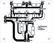
Peter: I'm going to use your schematic (see below) with the addition of an optional cap to buffer the pot.
I've already got the 12V PSU and the perfect pot so I'll literally just be switching out the PCBs for my tests.
🙂
Attachments
pietjers said:What voltage reference are you going to use?
I think a cap across the LED with a CCS is even more important than when driven by voltage, because LED noise is not suppressed by a CCS in any way.
Peter
I used 2 IN4002's for my ref ( powered by LM317.) They may not have absolute Vref performance compared with yours but all I am worried about is low noise in audio band - and on this I thought they would be at least as good - do you agree ?
I disagree on the caps because I tried it with CCS with and without caps and could hear little difference where as with V drive I heard a BIG difference. so my guess is that CCS controls LED noise very well.
> caddock TF020
> shinkoh tantalum
> vishay bulk foil
> any other suggestions welcome.
Caddock MK132 ?
Patrick
> shinkoh tantalum
> vishay bulk foil
> any other suggestions welcome.
Caddock MK132 ?
Patrick
Mike,
Of course you constructed a (well known) current source, but two diodes in series have nothing to do with a voltage reference! Even when fed by a CCS. The LM317 is used to push the performance of the reference even further. Put at least some electrolytics (100uF) and a film cap (100n) in parallel with the diodes to get a more stable situation. I am sure that you will hear the difference. But I recommend a real voltage reference.
See post #1001 for details
Peter
Peter,
I will check it out but I think you will find you have two forward biased diodes in your darlington BJT .. so if forward biased diodes are noisy surely you have a noise problem as well.
I am sure that the IN4002 diodes move around with temperature but are you saying that the diodes are actually noisy in the audio band compared to the the device you used ?
perhaps you are right - I do not know
I will try a cap across the diodes .. 🙂
mike
Peter, referring to your photo of the layout from post 1032, it appears you have used additional electrolytics around the CCS. Perhaps they are part of the power supply?
Badge said:Tom, do me a favor and add your resistor configuration to the layout George has posted. Thanks
Hi Badge,
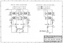
My attenuator test schematic, with all of the LTspice-specific stuff removed for clarity, is here:
http://www.fullnet.com/~tomg/att_sch.gif
That one's resistors were optimized for a 62k load resistance, just to try to get a good "spread" for various high and low load resistances.
Here is a plot of the input impedances for RLOAD = 22k (yellow), 62k (blue), 100k (red), and 1 Meg Ohms (other), as the attenuation pot setting is varied linearly from max to min attenuation, over a 3-second period, with R5 and R7 always kept equal to RLOAD:
http://www.fullnet.com/~tomg/ATT_VARR.GIF
Here is a similar plot, but with R5 and R7 always equal to 62k:
http://www.fullnet.com/~tomg/ATT_FIXR.GIF
Here is a similar plot, but with all of the linearizing resistors removed (i.e. R5, R8, R6, R4, R7, R9 removed):
http://www.fullnet.com/~tomg/ATT_NOR.GIF
Here is a similar plot, but with all of the linearizing resistors removed (i.e. R5, R8, R6, R4, R7, R9 removed), AND the power supply set back to 5v, from 5.3v. This should be like the original Lightspeed MkII:
http://www.fullnet.com/~tomg/ATT_5vnr.GIF
Badge:
The test setup was built on a piece of circuit board. That stuff is easy to work with and has good shielding properties. The assembled prototyping board I used for the test is originally made for a future amplifier. It contains two LM317 regulators (completely left) that are set at 12.6V to supply the filaments of the tubes of that amplifier.
The three TO-92 devices right of the blue cap is the CCS of one channel (TL431, LM317, BC550C). The other channel is under the grey/orange cable.
The blue potentiometer is to control the original Lightspeed and the metal pot is for the CCS version. I could switch between the two by just swapping the D-connector.
An externally hosted image should be here but it was not working when we last tested it.
CCS-version
Sorry for my dumb question. What is the CCS version again. I lost a little bit the overview.
I have built the LS MK2 version 6 month ago. One problem is the high min level and the little flatness at high attenuation. Rest is good!
What version sounds best?
What are input and output impedance?
Sorry for my dumb question. What is the CCS version again. I lost a little bit the overview.
I have built the LS MK2 version 6 month ago. One problem is the high min level and the little flatness at high attenuation. Rest is good!
What version sounds best?
What are input and output impedance?
Tolu:
This is the CCS version I designed. See post #1001 for details. I use it as a volume control of a tube amplifier (so not as a passive pre-amp). The attenuation range of the version with the fixed resistor is about 60dB. But as you can read in post #1001 the design leaves much room to suit your specific needs.
Peter
An externally hosted image should be here but it was not working when we last tested it.
Got to give this a try
This circuit looks very easy to build and I have the regulated 12 volt already. And the 100K log pots. I will try to put one together next week and listen against a voltage controlled one. If it is better sounding than a voltage controlled unit, it will be very special.
Also, to compare the effect of bypass caps on the sonics, trying moving them a little closer. Even a little lead length greatly increases the inductance and lowers the effect. I managed to solder mine almost to the leads on the LDR. Maybe 1 cm total lead length.
I am happy to see people trying novel deas on powering these circuits. Even a small increrase in resolution would be welcome.
George
- Home
- Source & Line
- Analog Line Level
- Lightspeed Attenuator a new passive preamp