yeah its already in the casing. the other thing is that 40 ohms from this LDR is about as low as any LDR will go.
What is the cheapest way to build pre amplifier based LDR for testing vs Alps blue?
Anyone thinking of selling one? 🙂
Anyone thinking of selling one? 🙂
George's Lightspeed circuit really couldnt get any less expensive unless you used a zener supply and no trimmers.
From memory this guy in his original ad said he just got a new production Lightspeed Attenuator from me, so he's selling his home made one, he's relisted it, and it's lower in price now.
Lightspeed attenuator - Canuck Audio Mart
Cheers George
Lightspeed attenuator - Canuck Audio Mart
Cheers George
Misunterstanding, sorry merlin I did not mean you said the one your selling is original, I said it was home made, (diy).
Cheers George
Cheers George
Brought one of my lightspeed attenuators to the local GTA meetup and unfortunately had bad luck as my voltage regulator started smoking.
I thought I had brought the wrong adapter, but I checked it and got about 17vdc out of it (it's rated for 12v).
I've got to replace my voltage regulator (L7805ABV), but should I replace my adapter too? Is it putting out more voltage than the regulator can handle?
I thought I had brought the wrong adapter, but I checked it and got about 17vdc out of it (it's rated for 12v).
I've got to replace my voltage regulator (L7805ABV), but should I replace my adapter too? Is it putting out more voltage than the regulator can handle?
The Lightspeed's internal regulator is 5vdc 1amp and can take from 8-20vdc what happened was the polartity of the wall wart you bought was most probably - negative centre instead of + positive centre, if so this would take out the first electro cap around 100uf 25v and also the L7805 regulator. Should cost no more than ten dollars from a electronics shop, just remember which way the regulator was and also the cap.
Cheers George
Cheers George
Better that there is a 1 amp series diode on the board, and appropriate instructions to constructors. Such a diode would alleviate dangerous reverse polarity circumstances
as can occur with reverse polarity and particularly electrolytic capacitors exposed to reverse polarity.
see; Troubleshooting analog circuits - Pease - Google Books
. 🙂 Cheers / Chris
as can occur with reverse polarity and particularly electrolytic capacitors exposed to reverse polarity.
see; Troubleshooting analog circuits - Pease - Google Books
. 🙂 Cheers / Chris
Yes, I noticed that a series diode in front of the regulator would have prevented reserve polarity problems. I've got a few 5v reg circuits I can pop right in as a replacement. I'll be sure to add a few diodes.
What about running it from 2x 9v batteries?
What about running it from 2x 9v batteries?
Yes, I noticed that a series diode in front of the regulator would have prevented reserve polarity problems. I've got a few 5v reg circuits I can pop right in as a replacement. I'll be sure to add a few diodes.
What about running it from 2x 9v batteries?
I run mine from a single 9v battery as a backup when I am messing up the regular supply. I just put a DC connector on the 9V just like the walwort so you can interchange. My standard is to run it from a linear power supply that is toroid to bridge rectifier then CLCRCLC filtered. Last but not least, 150uf Oscons right on the LDR pins also bumps it up. The linear supply is outboard and the last CLC filter before the low noise reg is onboard.
A battery has no ripple but actually a fairly high noise floor.
The regulator is a point to point zener emitter follower from TNT audio site. Also little bump in SQ over the 7805.
The quietest batteries I found were the rechargeable Lithium-Ion ones in the link, a 6800mA one last for weeks of listening before a 1/2hr recharge is needed. But please make sure if they are for the Lightspeed Attenuator I supply, that you ask the seller if the plug is 2.1mm to connect to the Lightspeed and that centre of the dc plug is + positive.
12vdc Li Rechargable | eBay
Cheers George
12vdc Li Rechargable | eBay
Cheers George
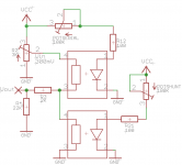
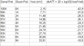
I want to add the level of attenuation of the Lightspeed Attenuator on my LCD-display, etched a little test-rig and measured Vout in relation
to the position of the wiper of the 100K potentiometer.
Since I do not own a precise 100K potentiometer I "simulated" it by 2 x 25 turns trim-potentiometers.
The reference input signal is 300mV. As a load I used the resistor input network (2K / 22K) of my FC-100 amplifier.
After 10 measurements I noticed that the LDRs behave very linearly.
A 1% decrease of the potentiometer's value (going from 100K -> 0K in 1K steps) results in a 1% increase (3mV) of Vout.
Is this really so? Do I have to measure any more?
Is my 300mV input signal a recommended value for any music-source?
Best regards - Rudi_Ratlos
Attachments
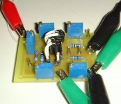
Hi Rudi, planning to offer your pcb board for sale. Thanks.This is my Lightspeed Attenuator PCB.
I have connected an OPAMP MCP6021 to the 100K potentiometer section wiper's output that drives the linear LDR.
Best regards - Rudi_Ratlos
Regards,
aeonsys
This is my Lightspeed Attenuator PCB.
I have connected an OPAMP MCP6021 to the 100K potentiometer section wiper's output that drives the linear LDR.
Best regards - Rudi_Ratlos
Rudi, I am looking at your photograph and the MCP602x datasheet. I guess the 8 pin DIP in the upper right corner is your 6021, but I can't visualize the function of a single op-amp in a circuit where there are two pot sections and four legs to be controlled. If the purpose was to offload managing the current from the pot onto the op-amp, I would think you'd use a 6022 or 6024 with two or four amps, so that can't be it. Could you tell me what that single op-amp does, please?
ebay lightspeed
hmm...
DIY PCB Light Speed Attenuator LDR NSL 32SR2 Pot Potentiometer Stepped Step | eBay
hmm...
DIY PCB Light Speed Attenuator LDR NSL 32SR2 Pot Potentiometer Stepped Step | eBay
- Home
- Source & Line
- Analog Line Level
- Lightspeed Attenuator a new passive preamp