what is the voltage with the circuit disconnected, i.e. no LED and no LDRs.
When I applied power it peaked at 15v and after 30 seconds the voltage settled at 14.92v
Tripmaster and I discussed this problem. We wondered whether it could be reverse voltage. Would a diode on the 7805 be worth doing in any event?
Tripmaster and I discussed this problem. We wondered whether it could be reverse voltage. Would a diode on the 7805 be worth doing in any event?
Yes. Ive just added a diode to the LED
15V at the smoothing cap with no load.
drops to 14.45V with the LDRs drawing current.
drops to 13.87V with the single LED added.
You need proper smoothing cap across the rectified supply.
Try 1000uF or somewhere close, 470uF to 2200uF.
Measure those three conditions again.
drops to 14.45V with the LDRs drawing current.
drops to 13.87V with the single LED added.
You need proper smoothing cap across the rectified supply.
Try 1000uF or somewhere close, 470uF to 2200uF.
Measure those three conditions again.
15V at the smoothing cap with no load.
drops to 14.45V with the LDRs drawing current.
drops to 13.87V with the single LED added.
You need proper smoothing cap across the rectified supply.
Try 1000uF or somewhere close, 470uF to 2200uF.
Measure those three conditions again.
Hi Andrew
I'm keeping you busy! 😀
Should I place this cap before the regulator, just after the green terminal block?
![url]](/community/proxy.php?image=http%3A%2F%2F%5Burl%3Dhttp%3A%2F%2Fimg15.imageshack.us%2Fi%2Fdaveslspeednd008.jpg%2F%5D%5Bimg%3Dhttp%3A%2F%2Fimg15.imageshack.us%2Fimg15%2F686%2Fdaveslspeednd008.th.jpg%5D%5B%2Furl%5D&hash=a53d3a4929660840dd65f8ce7f51ea75)
Hi
I added a 1000uf cap after the power supply terminal block today. It worked fine for a while but has blown another walwart!
I added a 1000uf cap after the power supply terminal block today. It worked fine for a while but has blown another walwart!
Member
Joined 2002
Hi
I added a 1000uf cap after the power supply terminal block today. It worked fine for a while but has blown another walwart!
I think there is something shorted out or something wrong with your circuit, are you able to post some pictures of this setup detailed pictures of your board and other things ?
Have you tried to measure the current draw from the psu with the volume pot ?
What are the spec's of your walwarts ?
Jase
I think there is something shorted out or something wrong with your circuit, are you able to post some pictures of this setup detailed pictures of your board and other things ?
Have you tried to measure the current draw from the psu with the volume pot ?
What are the spec's of your walwarts ?
Jase
Hi Jase
This is soooo infuriating. I don't like to give up too easily but this is starting to waste far too many power packs. I might just build one on perf board as it much easier to fault find. I find it hard to believe I've had so many problems with such a simple circuit 🙄
I'm not sure if these pictures are going to make it any easier for you...


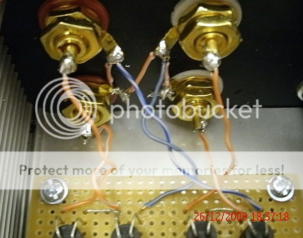
Have you tried to measure the current draw from the psu with the volume pot ? NO
Thanks for your interest!
Member
Joined 2002
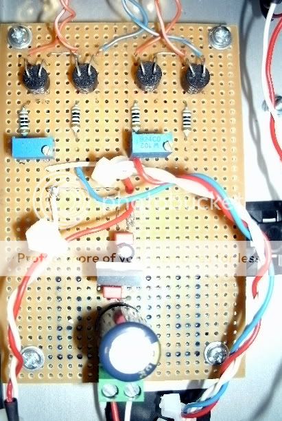
is this a switch ?
I don't think it's suppose to be connected that way, it should be in series not parallel, that might be the problem right there. Wire the power adapter right to the board, if you can put the meter in series on the current measuring mode and see how much current is being drawn.
Edit, infact take that whole thing out of the loop the connector and the switch and just wire the adapter to the board first.
J'
is this a switch ?
I don't think it's suppose to be connected that way, it should be in series not parallel, that might be the problem right there. Wire the power adapter right to the board, if you can put the meter in series on the current measuring mode and see how much current is being drawn.
J'
Yes it is a switch
Member
Joined 2002
Yes it is a switch
remove it and the plug, wire your new psu right to the board, bet this is the problem right there.
J'
Thanks!
Can I leave the DC inlet socket as I don't have any small grommets?
Is there anything else I can measure/do to see if I have a fault?
Can I leave the DC inlet socket as I don't have any small grommets?
Is there anything else I can measure/do to see if I have a fault?
Member
Joined 2002
Thanks!
Can I leave the DC inlet socket as I don't have any small grommets?
Is there anything else I can measure/do to see if I have a fault?
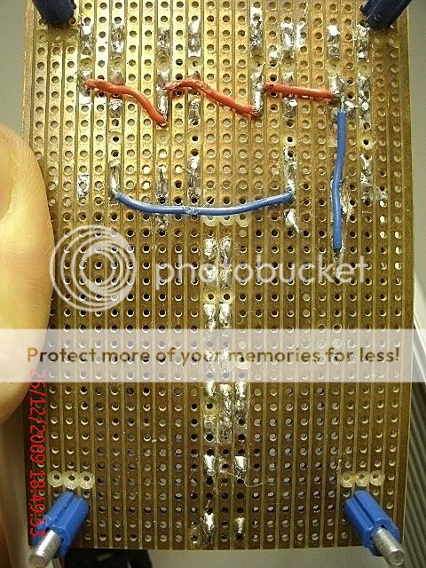
for now its not time to make it look pretty 🙂 just remove the top cover and wire the power supply right to the board. If it works then ill show you your error 🙂
( just in case ) i can see it working 100% too, it looks like your switch is wired to short your psu, 🙂
Try it wired directly to the board, remove the plug and switch, if works post back 🙂
'For now its not time to make it look pretty 🙂' Fair point 😱
All done, and hopefully not burning-out on the work bench😀
Cutting of the DC jack from an adapter has certainly widen my choice 😉
I'll keep you posted.
All done, and hopefully not burning-out on the work bench😀
Cutting of the DC jack from an adapter has certainly widen my choice 😉
I'll keep you posted.
Member
Joined 2002
'For now its not time to make it look pretty 🙂' Fair point 😱
All done, and hopefully not burning-out on the work bench😀
Cutting of the DC jack from an adapter has certainly widen my choice 😉
I'll keep you posted.
Just remember we are just doing this to try it out, thats all. If it works then your good to next step, i can almost bet that, the switch was the problem, i see it wired in parallel not series.
Jase
- Home
- Source & Line
- Analog Line Level
- Lightspeed Attenuator a new passive preamp