I dont think you can balance with the Alps control. It is easy that way though. I bought the Alps kit but have yet to get it in a box. Matching is all my DIY right now. Cant wait to be done with it and build something.
Uriah
Uriah

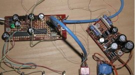
Heres a few pics of the modules from Paul, its housed in a small aluminum enclosure. The infra red transmitter is enclosed inside a plastic project box fed from AA batteries, keypad is made by Storm from Farnell
The remote is big and junky but does the job😀


The vol adjustments is nice and smooth, I keep my finger held down on the up button until the sound is audible, I then tap it until its at the required volume
The balance control is a handy feature, it seems to work well for the less than perfect matched LDR's, mine was a little off centre, a few taps on the balance sorted it nicely.
The volume and balance re-sets after power cycling
I'm really pleased with this thing, sound quality is better than any of my normal pots (Alps blue and black) and also betters my Vishay Dale Attenuator
Big thanks to George for sharing this design and also to Paul Hynes for making these cool modules available to us diyers😎
The remote is big and junky but does the job😀
The vol adjustments is nice and smooth, I keep my finger held down on the up button until the sound is audible, I then tap it until its at the required volume
The balance control is a handy feature, it seems to work well for the less than perfect matched LDR's, mine was a little off centre, a few taps on the balance sorted it nicely.
The volume and balance re-sets after power cycling
I'm really pleased with this thing, sound quality is better than any of my normal pots (Alps blue and black) and also betters my Vishay Dale Attenuator
Big thanks to George for sharing this design and also to Paul Hynes for making these cool modules available to us diyers😎
ASLHK said:We will supply LDR attenuator moudule
Who are "we"?
I see a lot of AntiqueSoundLab amps on your site?

Thanks ASLHK for flagging your post. 🙂
You can describe your products in the Vendors Bazaar forum.
input impedance for active x-over
Hi george,
I will be building an active x-over after the lightspeed. I was wondering is the input impedance important? Any more important areas to look out for before I start my x-over? 😕
Thanks
KK
Hi george,
I will be building an active x-over after the lightspeed. I was wondering is the input impedance important? Any more important areas to look out for before I start my x-over? 😕
Thanks
KK
Remember the string ...
It's all about impedances - What version of Lightspeed and what Xover? (Cct)
It's all about impedances - What version of Lightspeed and what Xover? (Cct)
KK hi, if you are building the same as my production Lightspeed Attenuator MkII, your input impedance on your xover should try to be 50kohms or higher, if using 50k keep the interconects at 1mtr or less, otherwise you will be right.
And please vote here for our own passive preamp (attenuator) forum. http://www.diyaudio.com/request/
Cheers George
And please vote here for our own passive preamp (attenuator) forum. http://www.diyaudio.com/request/
Cheers George
Hi,
you must ensure that the first filter stage is not compromised by the high source impedance of the preceding stage.
i.e. you must fit a buffer. Normally active crossovers have just such a buffer at the input. If your's does not, then a buffer must be fitted either at the source or at the receiver.
you must ensure that the first filter stage is not compromised by the high source impedance of the preceding stage.
i.e. you must fit a buffer. Normally active crossovers have just such a buffer at the input. If your's does not, then a buffer must be fitted either at the source or at the receiver.
now built the VCCS
I used LM317L as CCS(8ma) instead of the JFET, and use LM336-5 instead of the middle TL431 for 5V reference. The balance control works great.
With SR3, Zout is around 2-4K. Zin is around 20K-100K when using -20 to -30db range of the DS1802. Probably need to put a serial resistor (1K) from DS1802 L0/L1 to 3.3V to better utilize the -50db to -30 db of the digital POT. Right now I have to click 30-40 times to the volume I need.
Next step is to add remote, I saw some cheap 4 button RF remote control with Relays, do I need to care about the interference from RF?
Anyway, thanks Paul for the great design.
Attachments

Lightspeed Remote control
Hi 2A3SET,
Nice work on the boards. I'm pleased you have got the circuit operating well. In principal an RF transmitter/receiver should work but, as I haven't tried any, I do not know if you will face iny interference problems.
Out of interest I made the VCCs circuit board layout adaptable to use a precision current source instead of the depletion mosfet, low noise precision shunt regulators in place of the TL431 shunt regulators and a low noise series regulator in place of the 7812 as there had been comments about power supply quality very early on the forum thread before I set up the group buy for the remote control. It was my intention to set up a VCCS module to try these power supply upgrades against a standard issue VCCS module to see how sensitive the VCCs circuit is to power supply quality. Unfortunately I have been very busy with work which has overlapped into my free time preventing me from do the trial. Once I have caught up with my work load I will schedule a test with these power supply upgrades and report the results.
Regards
Paul
Re: Tried the CCS version first
Hi, Lao Zhu
2A3SET said:MK1 CCS with SR3.
Serial resistors are TX2575, CADDOCK TF020 and Shinkoh
Hi, Lao Zhu
Have been experimenting with LM334. For some reason when I drive them with this the matched pairs no longer match. HOWEVER I can go super high in Ohms. I got control into the MegOhms. Will have to try matching my next batch using LM334 and work up a little supply/control circuit for you guys to try. Also considering using LM385 with 2n2905 and 2n3962. You can find the circuit in the LM385 datasheet. It will supply 1uA to 100mA. Giving it a try probably tonight. Couldnt get it to work yesterday for some reason but LM334 was successful.
Uriah
Uriah
Thanks guys for your feedback.
I will be doing a Lightspeed MkII and a Linkwitz-Riley Crossover from ESP. I was thinking about using the LM4562 with a 100k input impedance. Anyone have any other suggestion?😕
I will be doing a Lightspeed MkII and a Linkwitz-Riley Crossover from ESP. I was thinking about using the LM4562 with a 100k input impedance. Anyone have any other suggestion?😕
recommend to use matching in CCS circuit
I noticed the matching pair done with LM334 doesn't match that great in CCS circuit as well, so it should be ideal just use CCS circuit to match the LDR, just raise the LDR/BC517 side voltage to higher so you can match more pairs together.
I noticed the matching pair done with LM334 doesn't match that great in CCS circuit as well, so it should be ideal just use CCS circuit to match the LDR, just raise the LDR/BC517 side voltage to higher so you can match more pairs together.
- Home
- Source & Line
- Analog Line Level
- Lightspeed Attenuator a new passive preamp